3MAINTENANCE__O.pdf - 第95页
3.4 Device Test 3.4 . 1 X / Y Table Test When the [ X / Y TABLE TEST ] key is pressed at the “ DEVICE TEST ” display , the following display appears on the screen . : 12 丽 8 ( 123 Mbm CURRENT PRGM : STEP NO . STATUS READ…
3.4
Device
Test
3.4
Device
Test
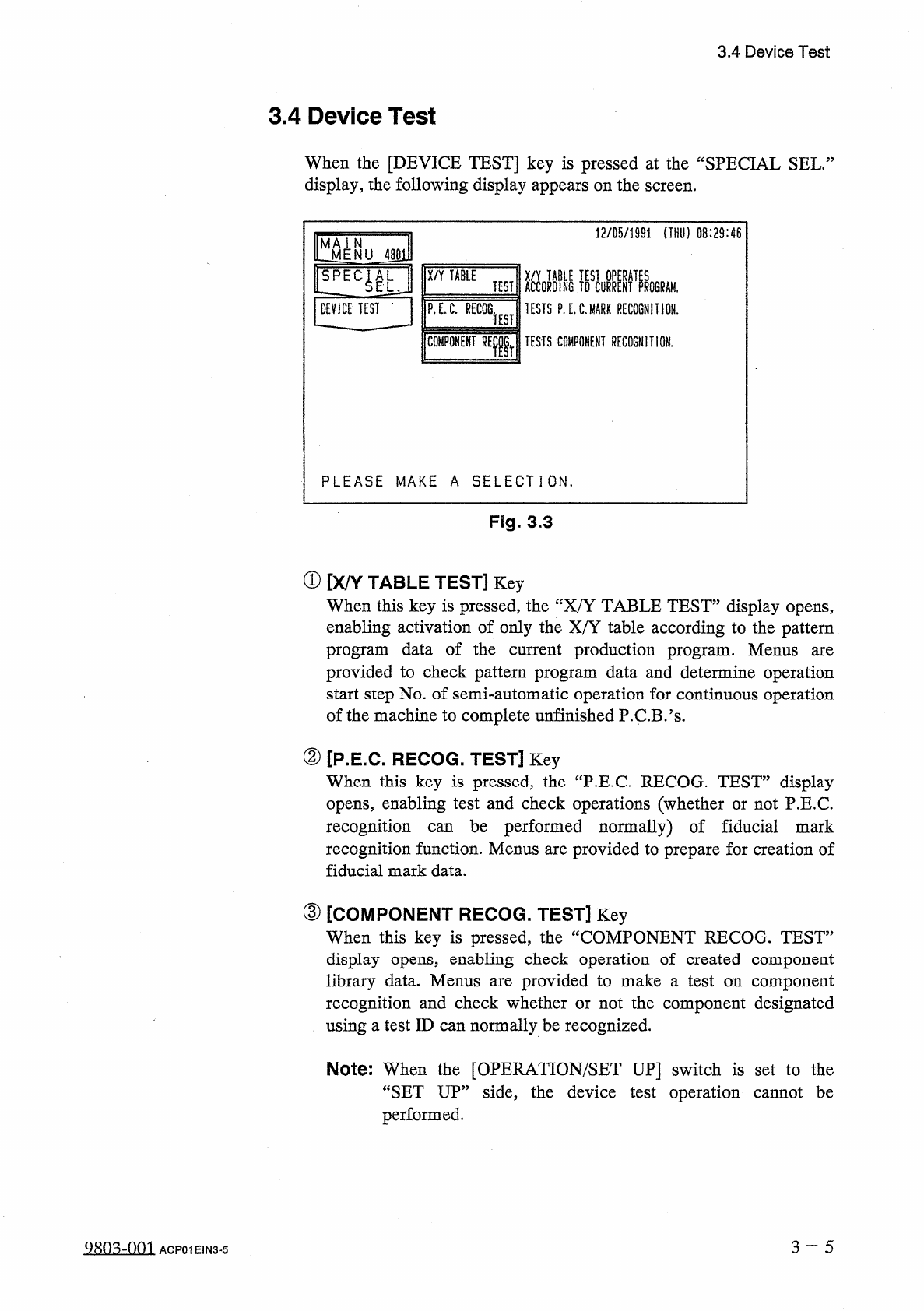
When
the
[
DEVICE
TEST
]
key
is
pressed
at
the
“
SPECIAL
SEL
.
display
,
the
following
display
appears
on
the
screen
.
12
/
05
/
1991
(
THU
)
08
:
29
:
46
^
MENU
48
E
X
/
Y
TABLE
ACCORDING
TESTS
P
.
E
.
C
.
MARK
RECOGNITION
.
TEST
!
ROGRAM
.
DEVICE
TEST
-
P
.
E
.
C
.
RECOG
.
TEST
COMPONENT
RElr
TESTS
COMPONENT
RECOGNITION
.
PLEASE
MAKE
A
SELECTION
.
Fig
.
3.3
①
[
X
/
Y
TABLE
TEST
]
Key
When
this
key
is
pressed
,
the
“
X
/
Y
TABLE
TEST
”
display
opens
,
enabling
activation
of
only
the
X
/
Y
table
according
to
the
pattern
program
data
of
the
current
production
program
.
Menus
provided
to
check
pattern
program
data
and
determine
operation
start
step
No
.
of
semi
-
automatic
operation
for
continuous
operation
of
the
machine
to
complete
unfinished
P
.
C
.
B
.
’
s
.
are
②
[
P
.
E
.
C
.
RECOG
.
TEST
]
Key
When
this
key
is
pressed
,
the
“
P
.
E
.
C
RECOG
.
TEST
”
display
opens
,
enabling
test
and
check
operations
(
whether
or
not
P
.
E
.
C
.
recognition
recognition
function
.
Menus
are
provided
to
prepare
for
creation
of
fiducial
mark
data
.
be
performed
normally
)
of
fiducial
mark
can
③
[
COMPONENT
RECOG
.
TEST
]
Key
When
this
key
is
pressed
,
the
“
COMPONENT
RECOG
.
TEST
”
display
opens
,
enabling
check
operation
of
created
component
library
data
.
Menus
recognition
and
check
whether
or
not
the
component
designated
using
a
test
ID
can
normally
be
recognized
.
provided
to
make
a
test
on
component
are
Note
:
When
the
[
OPERATION
/
SET
UP
]
switch
is
set
to
the
“
SET
UP
”
side
,
the
device
test
operation
cannot
be
performed
.
3
~
5
Q
8
n
.
^
-
nni
ACP
01
EIN
3
-
5
3.4
Device
Test
3.4
.
1
X
/
Y
Table
Test
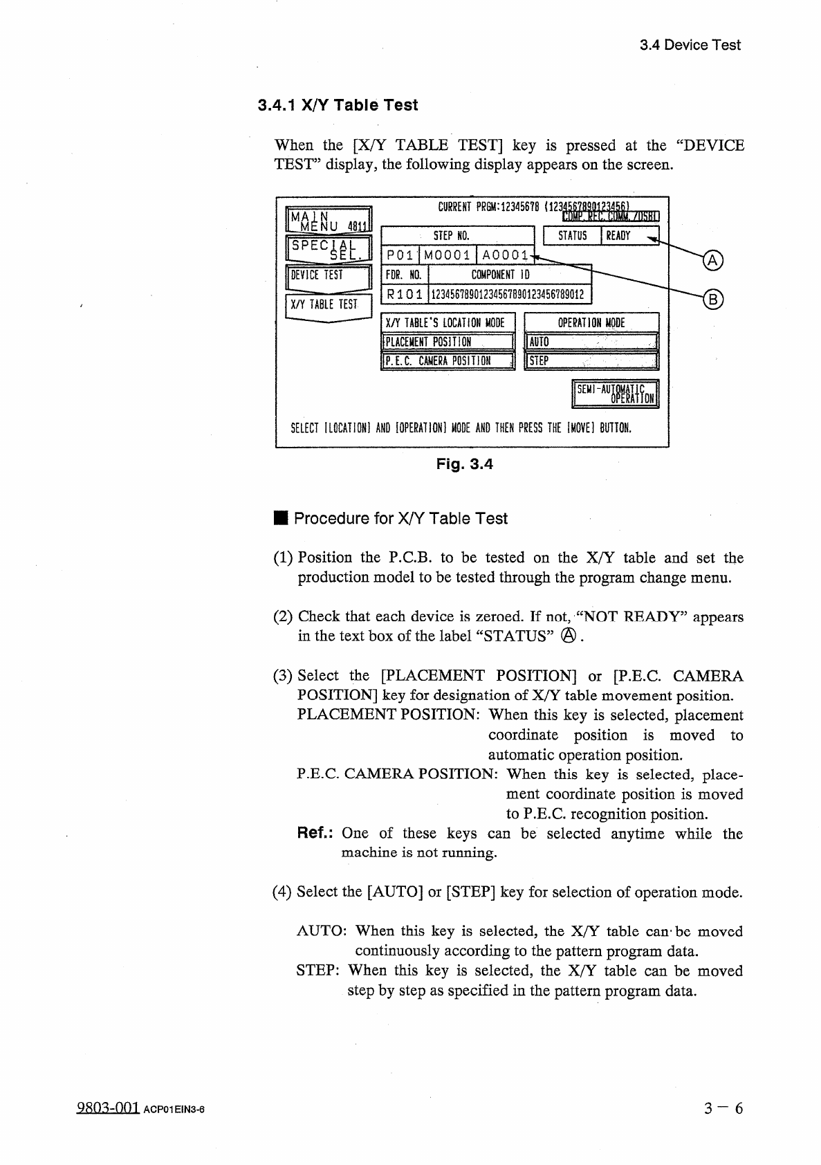
When
the
[
X
/
Y
TABLE
TEST
]
key
is
pressed
at
the
“
DEVICE
TEST
”
display
,
the
following
display
appears
on
the
screen
.
:
12
丽
8
(
123
Mbm
CURRENT
PRGM
:
STEP
NO
.
STATUS
READY
P
01
-
MOOOl
AOOOl
DEVICE
TEST
COMPONENT
ID
FDR
.
NO
.
R
1 0 1
12345678901234567890123456789012
B
X
/
Y
TABLE
TEST
X
/
Y
TABLE
'
S
LOCATION
MODE
IPLACEMEHT
posmor
OPERATION
MODE
爾
1
P
.
E
.
C
.
CMIERA
POSITIOH
j
[
STEP
'
SEHI
~
AUIiW
SELECT
IL
0
CATI
0
N
1
AND
[
OPERATION
]
«
AND
THEN
PRESS
THE
IM
0
VE
1
BUTTON
.
Fig
.
3.4
■
Procedure
for
X
/
Y
Table
Test
(
1
)
Position
the
P
.
C
.
B
.
to
be
tested
on
the
X
/
Y
table
and
set
the
production
model
to
be
tested
through
the
program
change
menu
.
(
2
)
Check
that
each
device
is
zeroed
.
If
not
,
“
NOT
READY
”
appears
in
the
text
box
of
the
label
“
STATUS
”
•
(
3
)
Select
the
[
PLACEMENT
POSITION
]
POSITION
]
key
for
designation
of
X
/
Y
table
movement
position
.
PLACEMENT
POSITION
:
When
this
key
is
selected
,
placement
coordinate
position
is
moved
to
automatic
operation
position
.
P
.
E
.
C
.
CAMERA
POSITION
:
When
this
key
is
selected
,
place
-
ment
coordinate
position
is
moved
to
P
.
E
.
C
.
recognition
position
.
Ref
-
:
One
of
these
keys
can
be
selected
anytime
while
the
machine
is
not
running
.
[
P
.
E
.
C
CAMERA
or
(
4
)
Select
the
[
AUTO
]
or
[
STEP
]
key
for
selection
of
operation
mode
.
AUTO
:
When
this
key
is
selected
,
the
X
/
Y
table
can
'
be
moved
continuously
according
to
the
pattern
program
data
.
STEP
:
When
this
key
is
selected
,
the
X
/
Y
table
can
be
moved
step
by
step
as
specified
in
the
pattern
program
data
.
2
SQ
3
ZQQ
1
3
一
6
ACP
01
EIN
3
-
6
3.4
Device
Test
(
5
)
The
X
/
Y
table
test
starts
.
When
the
[
AUTO
]
key
is
selected
,
the
following
action
takes
place
.
•
When
the
[
MOVE
]
button
is
pressed
,
the
X
/
Y
table
test
operation
(
continuous
operation
based
on
pattern
program
data
)
starts
.
•
When
the
[
STOP
]
button
is
pressed
,
the
X
/
Y
table
moves
as
far
up
as
to
the
last
step
of
the
pattern
program
data
,
returns
to
its
origin
,
and
stops
.
•
When
the
[
PAUSE
]
button
is
pressed
,
the
X
/
Y
table
stops
temporarily
.
When
the
[
STEP
]
key
is
selected
,
the
following
action
takes
place
.
•
Every
time
the
[
MOVE
]
button
is
pressed
,
the
X
/
Y
table
moves
by
a
step
.
Ref
.
:
As
the
step
No
.
displayed
in
®
is
reflected
upon
the
operation
starting
step
at
the
“
AUTO
OPERATION
(
STEP
)
,
,
display
,
use
this
to
continue
processing
of
unfinished
P
.
C
.
B
/
s
caused
due
to
power
OFF
,
etc
.
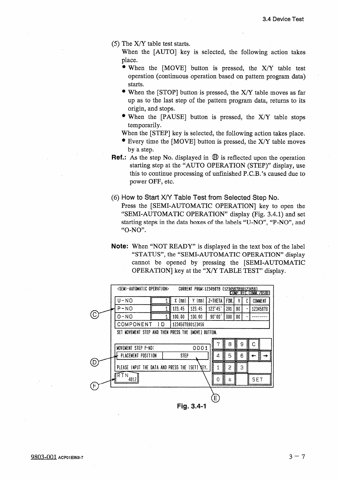
(
6
)
How
to
Start
X
/
Y
Table
Test
from
Selected
Step
No
.
Press
the
[
SEMI
-
AUTOMATIC
OPERATION
]
key
to
open
the
“
SEMI
-
AUTOMATIC
OPERATION
”
display
(
Tig
.
3.4
.
1
)
and
set
starting
steps
in
the
data
boxes
of
the
labels
“
U
-
NO
”
,
“
P
-
NO
”
,
and
“
O
-
NO
”
.
Note
:
When
“
NOT
READY
”
is
displayed
in
the
text
box
of
the
label
“
STATUS
”
,
the
“
SEMI
-
AUTOMATIC
OPERATION
”
display
cannot
be
opened
by
pressing
the
[
SEMI
-
AUTOMATIC
OPERATION
]
key
at
the
“
X
/
Y
TABLE
TEST
”
display
.
<
SEMI
-
AUTOMATIC
OPERATION
)
CURRENT
PR
8
M
:
12345678
1123
WM
-
/
勵
II
3
U
-
NO
X
(
dim
)
Y
(
di
)
Z
=
THETA
FOR
.
V
C
COMMENT
3
P
-
NO
123.45
123.45
123.45
.
201
00
12345678
2
90
*
00
*
O
-
NO
100.00
100.00
000
COMPONENT
ID
1234567890123456
SET
MOVEMENT
STEP
AND
THEN
PRESS
THE
[
MOVE
]
BUTTON
.
7
8
9
C
MOVEMENT
STEP
P
-
NO
:
0001
]
PLACEMENT
POSITION
STEP
4
5
6
PLEASE
INPUT
THE
DATA
AND
PRESS
THE
ISET
1
XEY
.
2
3
1
TR JH
mi
0
SET
土
E
Fig
.
3.4
-
1
3
-
7
9803
-
001
ACP
01
EIN
3
-
7