Nordson_EFD_781RC_Quick_Start_Guide
781RC Micr oMark Recir culating Spray Marking System Quick Start Guide Electronic pdf les of Nor dson EFD manuals are also available at nordsonefd.com ™
781RC MicroMark Recirculating Spray Marking System
Quick Start Guide
Electronic pdf les of Nordson EFD
manuals are also available at
nordsonefd.com
™
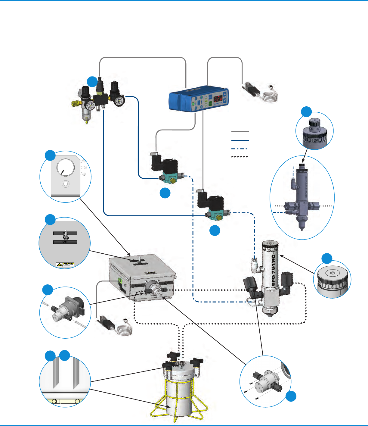
Prior to installing the MicroMark
®
Recirculating Spray Marking System, read the associated spray valve and valve
controller operating instructions to become familiar with the operation of all components of the spray system.
Select an appropriate system setup location for all system components — pump enclosure, 1-liter reservoir,
ValveMate
™
8040, and 781RC* spray valve.
Turn the pump enclosure power switch (6c) to OFF and ensure that the speed control (6a) is turned fully
counterclockwise to the OFF position.
*The 781RC system is also available with
a 787MS-SS-RC MicroSpray
™
valve.
Setup is exactly the same regardless of
the valve type. Contact EFD for details.
1
2
3
4
5
10
5
6a
6c
Electric
Air Constant
Air Pulse
Fluid
787MS-SS-RC
781RC
7
7
781RC MicroMark Recirculating Spray Marking System
2 www.nordsonefd.com info@nordsonefd.com 800-556-3484 Sales and service of Nordson EFD dispensing systems are available worldwide.
1. Cut feed tube hose to desired length and install into tank
lid outlet port. Insert tube to bottom of tank liner. Cut tube
at slight angle to avoid uid blockage at bottom of tank.
2. Connect the uid supply line from tank outlet to pump inlet
compression tting.
3. Connect the uid line from pump outlet to the 781RC inlet
port compression tting.
4. Cut recirculation feed hose to desired length and install
into tank lid recirculation port. Insert recirculation hose to
bottom of 1 liter liner.
Cut tube at slight angle to avoid uid blockage at bottom
of tank. Attach other end to 781RC recirculation port outlet
compression tting.
5. Connect the control air hose and the nozzle air hose to
corresponding outputs on solenoid block. Reference
VM8040 Quick Start Guide.
6. Fill reservoir by pouring uid directly into tank liner or
manufacturer’s bottle placed inside reservoir. Secure cover.
a. Conrm the speed control knob is OFF by turning fully
counterclockwise.
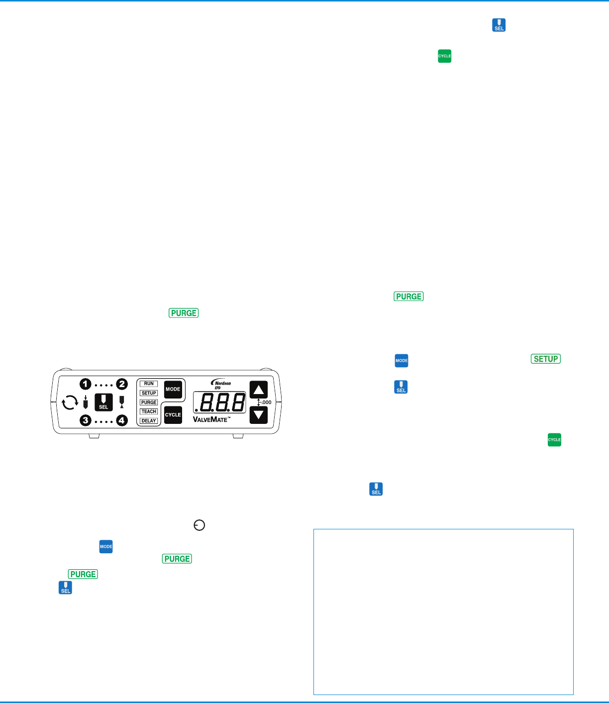
b. Set ValveMate 8040 to Mode.
c. Turn pump enclosure power switch to ON.
7. Turn 781RC valve stroke to no less than 1/2 turn or more
open.
SPRAY VALVE CONTROLLER
8040
8. Priming the pump (important note: dry running time should
be kept to an absolute minimum). During initial startup,
keep pump speed low — approximately 9 o’clock position
— until uid reaches the pump.
9. Once 781RC is fully primed, set speed control to
approximately 9 o’clock position.
10. Using the button on the ValveMate 8040 controller,
place the controller in the mode.
In mode only, channels 1 and 3 can be selected
independently without nozzle air pressure.
11. Once proper ow is established, press until all
channels are active.
Depress ValveMate 8040
button and adjust speed
control to set uid ow rate to one or two drops per
second.
NOTE: Flow adjustments should be made with speed
control as apposed to reductions of valve needle stroke.
Tight valve stroke settings will cause blockage / clogging
of valve outlet.
12. Set the nozzle air pressure on the nozzle to 0.7 bar (5 psi)
and actuate the controller. Adjust higher as needed to
create even spray. The valve will produce a ne spray.
To change uid ow, use the needle stroke control knob
and/or pump speed control. Maintain balanced settings.
NOTE: Do not set stroke too tightly as this will cause
nozzle clogging.
To change nozzle air, use the nozzle air pressure regulator.
Higher pressures will provide ner spray.
13. Adjusting the spray.
a. Set the nozzle air pressure regulator to 0.7 bar (5 psi).
b. Press the button and observe the spray
pattern.
c. Using the spray valve stroke adjustment and pump
speed control, increase or decrease settings to arrive
at the desired spray pattern.
d. Using the button, place the controller in
mode.
e. Press the button repeatedly until all valve indicator
lights are lit.
f. Enter a spray time of 0.050 seconds by pressing the
up or down arrow next to the LED screen.
g. With a container still under the valves, press the
button to test the deposit amount.
h. Increase or decrease the valve open time to arrive at
the correct deposit size. To equalize all valves, press
the
button to highlight individual valves and use
the valve open time to equalize the output.
Final Checklist
1. Air pressure to solenoid pack is set to 5.5 bar (80 psi).
2. For spray valves, nozzle air regulator is set to 0 bar
(0psi).
3. Solenoids and I/O are wired correctly.
4. Valves and uid reservoir are properly connected.
5. Power to the ValveMate is on, and indicator lamps and
LED are lit.
781RC MicroMark Recirculating Spray Marking System
3www.nordsonefd.com info@nordsonefd.com 800-556-3484 Sales and service of Nordson EFD dispensing systems are available worldwide.