KE2040 Instruction Manual_ver1.30.pdf - 第310页
4 – 208 ① <FEED> button This butt on knock s a feeder once to f eed a component ( except a 32-mm paper tape). ② “Update pick data with new coordinates” Check this check box to use the HO D device and store the taug…
4 – 207
4.12.3.4.2 Vision recognition inspection operation
(1) Vision recognition operation
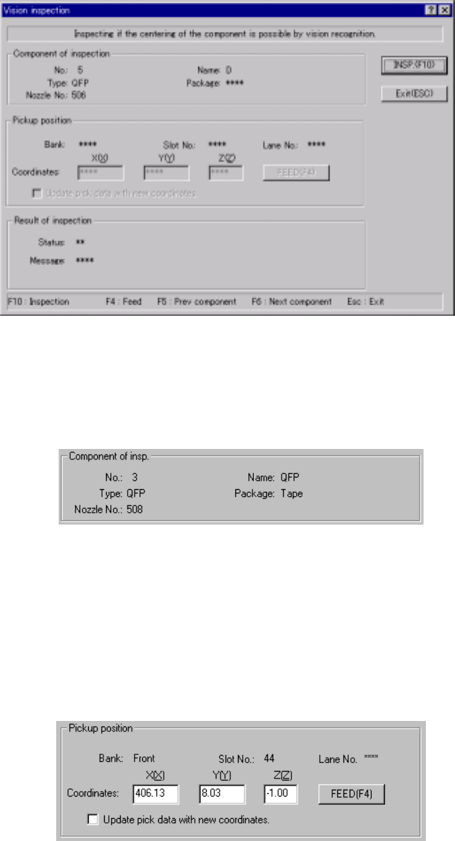
When you select the [Vision recognition] command, the following dialog box
appears on the screen.
Figure 4.12.3.4.2 “Vision inspection” dialog box
1) Component of insp. (inspection)
Component data required to perform the vision recognition inspection
appears on the dialog box.
Figure 4.12.3.4.3 “Component of insp.” Section
2) Pickup position
Data on the component pick-up position appears on the dialog box. You
can change the component pick-up position to the previous or next
alternate component position also. If there is no Pick data created, or if
“MTC” is specified as a feeder, each item on this section is not displayed,
so you cannot change the component pick-up position, perform the
feeder-knock operation or teaching operation.
Figure 4.12.3.4.4 Pick-up position of a component to be checked
4 – 208
① <FEED> button
This button knocks a feeder once to feed a component (except a 32-mm
paper tape).
② “Update pick data with new coordinates”
Check this check box to use the HOD device and store the taught result in
Pick data.
If you do not check this box, the taught coordinates are applied to the
current pick-up operation only.
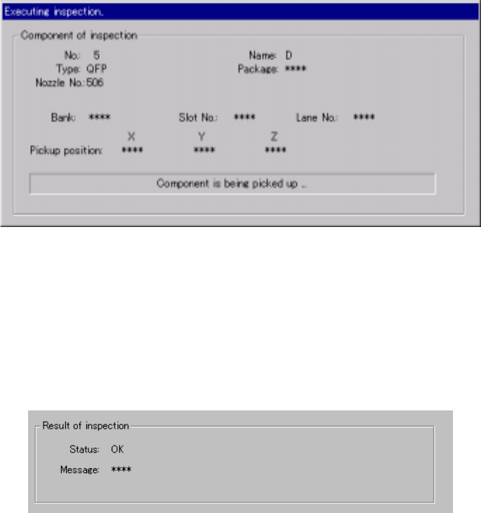
3) “Executing inspection” screen
While the system is checking a component with the vision recognition
function, the following dialog box appears on the screen. On this dialog
box, data on a component being inspected and its pick-up position are
displayed. The process being performed is also displayed.
Figure 4.12.3.4.5 “Executing inspection” screen
4) Result of inspection
After checking a component, the system displays the result in the “Result
of inspection” section of the screen. “OK” appears if a component can be
centered based on its vision, while “NG” and the reason of an error
appear in the “Message” space if not.
Figure 4.12.3.4.6 “Result of inspection” section
5) <INSP.> button
This button checks a component with the vision recognition function.
6) <Exit (ESC)> button
This button finishes checking a component with the vision recognition
function and returns to the previous screen.
4 – 209
7) Short-cut keys
The following short-cut keys are available on the “Vision inspection”
screen.
Table 4.12.3.4.1 Available short-cut keys
Keyboard
Operation
panel key
HOD key Action
F10 ENTER Starts checking a component with the
vision recognition function.
F4 Knocks a feeder.
F5 PREVIOUS Previous alternate component
F6 NEXT Next alternate component
ESC CANCEL Returns to the previous screen.
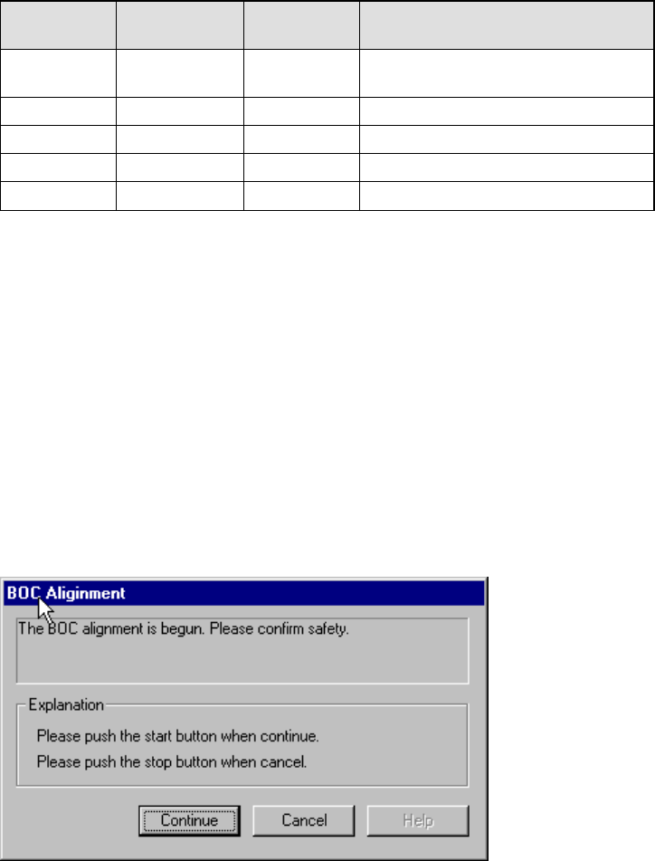
4.12.4 Confirmation
4.12.4.1 Mark - BOC
This command recognizes a BOC mark, then saves the measured coordinates of the
recognized BOC mark to the main unit. These measured coordinates are used to
correct coordinates during teaching of Placement data.
If the safety cover opens after you select the BOC command, the following dialog box
appears on the screen because the function to be invoked operates the axis.
Check the safety of the machine and yourself, then press the <Start> button.
Figure 4.12.4.1.1 BOC alignment - safety confirmation dialog box