KE2040 Instruction Manual_ver1.30.pdf - 第358页
5 − 16 5.2.3 Detailed description of operation W hen y ou invoke Vision data for t he firs t time, data appears in the “ Component name”, “ T ype”, “SizeX” and “SizeY” cells only . Figure 5.2.3. 1 Vision data ini tial sc…
5 − 15
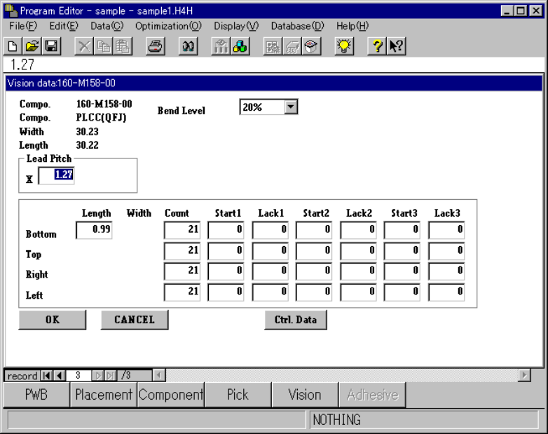
5.2.2.2 Vision Form
Sample Vision data and its basic operation are shown below.
Figure 5.2.2.2 Vision Form screen
◇ Description of basic operation
① Input focus
A line on which the input focus is located is reverse-displayed, while a cell in
which the input focus is located is not.
◇ An input character is echoed back onto the formula bar as you enter it.
When you validate it, it is entered in a cell.
② Cursor movement range
You can move the cursor to the items displayed on the screen only. To move
the input focus, press the <TAB> key or press the <SHIFT> key and <TAB>
key at the same time.
③ Setting items for which you do not have to enter any data
The items to which you do not have to enter any data show their respective
values on the screen.
5 − 16
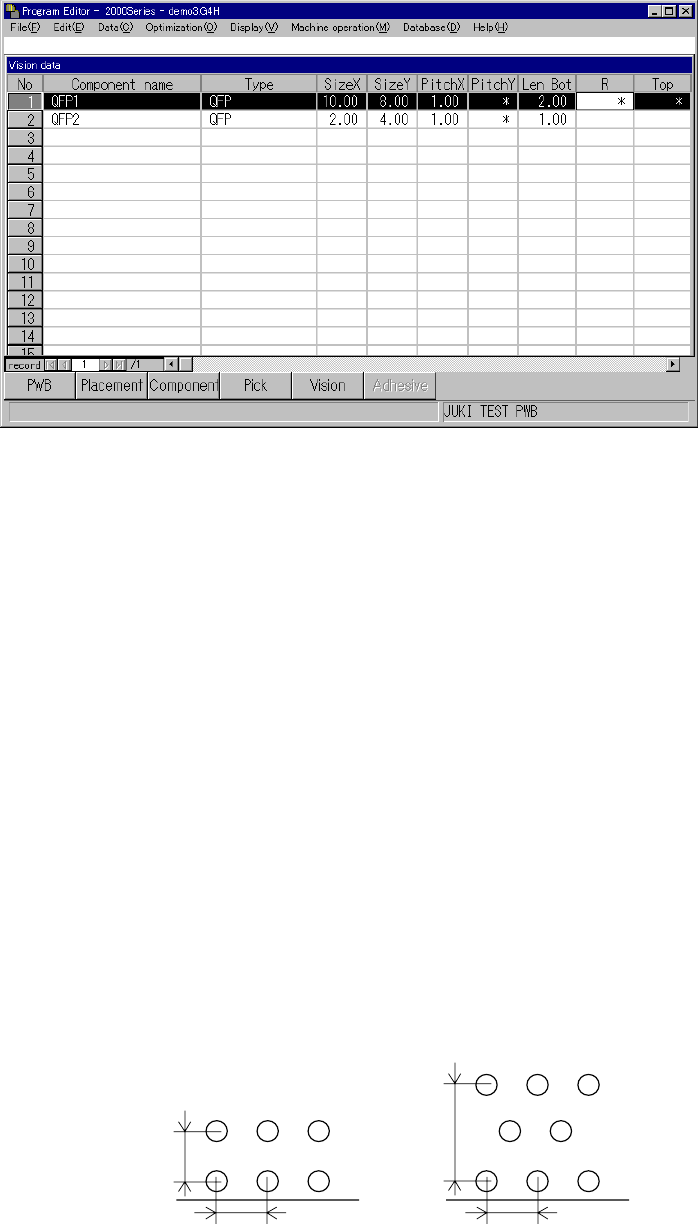
5.2.3 Detailed description of operation
When you invoke Vision data for the first time, data appears in the “Component
name”, “Type”, “SizeX” and “SizeY” cells only.
Figure 5.2.3.1 Vision data initial screen
(1) How to set the items
① Component name
A component name entered on the Placement data screen appears in this cell.
② Type
A component type entered on the Component data screen appears in this cell.
③ Size X
The width of a component, which was entered on the Component data screen,
appears in this cell.
④ Size Y
The length of a component, which was entered on the Component data screen,
appears in this cell.
⑤ 1) PitchX
Enter the horizontal pitch between two consecutive leads (balls) from the
formula bar. The input range varies depending on the component type.
2) PitchY
Enter the vertical pitch between two consecutive leads (balls) from the
formula bar. The input range varies depending on the component type.
Figure 5.2.3.2 Pitches applied to each component type
Ball pitch
(Normal assignment)
Ball pitch
(Stagger assignment)
5 − 17
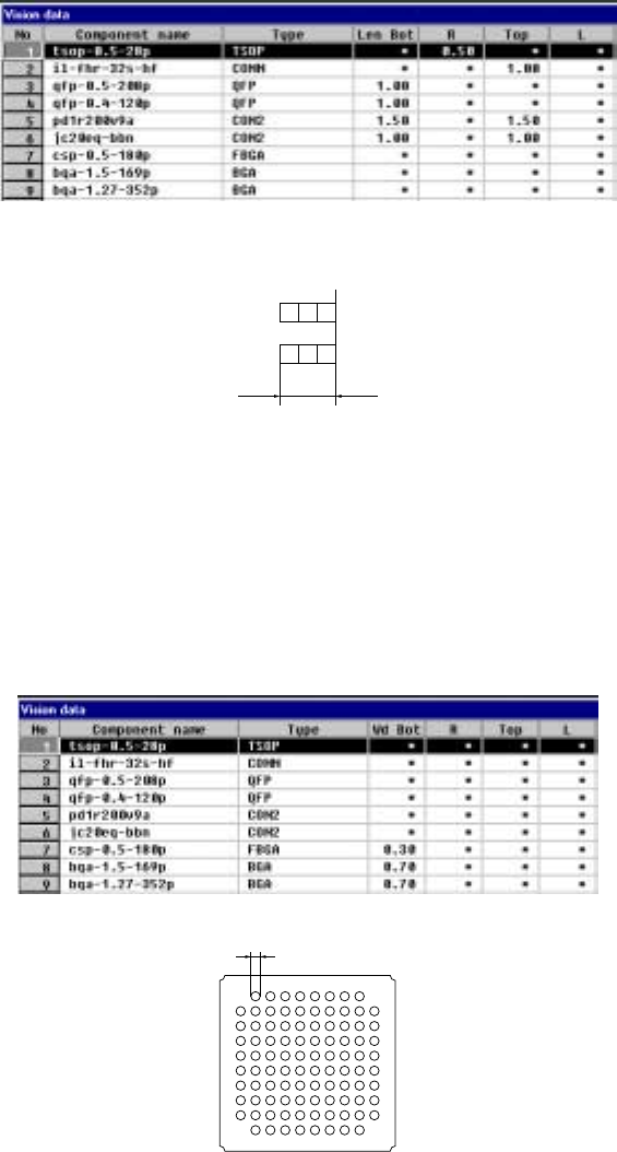
⑥ Len Bot, R, Top and L
Enter the length of a lead section that is in contact with a board from the
formula bar. When an asterisk mark * is displayed in a cell, you do not have
to enter any data to this cell.
- When a component has leads on its two or more sides, enter the length of a
lead on one side only if the length of leads on each side is the same as
each other.
- Data in the “Bot, R, Top and L” cells is based on the component feeding
angle with referring the final component feeding direction.
• The side whose lead length should be entered and the range of
the lead length vary depending on the setting of the “Type” item.
Figure 5.2.3.3 Entering the lead length from the formula bar
Lead length
Figure 5.2.3.4 Range of the lead length
⑦ Wd Bot, R, Top, L (lead or ball width)
Set the width of leads on each side: bottom, right, top and left sides in this
order. The side whose lead width should be entered and the range of the
lead width vary depending on the setting of the “Type” item.
• For a ball component, enter the diameter of a ball.
Figure 5.2.3.5 Entering the lead (ball) width
Ball width
Figure 5.2.3.6 Lead (ball) width