KE2040 Instruction Manual_ver1.30.pdf - 第364页
5 − 22 3) Limitation on component s depending on t he recognit ion method (A) Sid e recognition Recognition conditions: ① Components whose whole shape is a rectangle or reg ular sq uare ② Components whose linear portion …
5 − 21
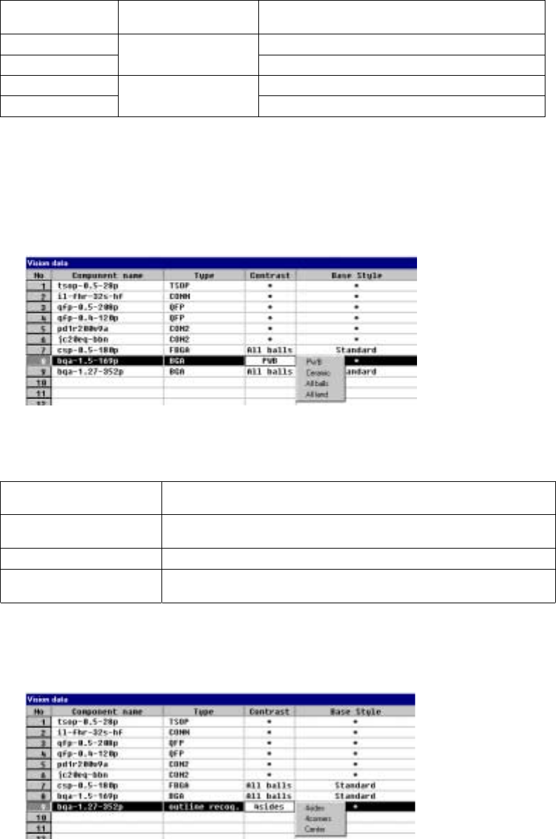
⑪ Contrast
Set the “contrast between a pin (ball) and molding section of a BGA
component”, or set the “recognition pattern for an outline-recognized
component”.
1) For a BGA
• Setting items
Table 5.5.3.1
Selection on the
pop-up menu
Recognition range Type
PWB PWB type whose molding section looks black
Ceramic
Recognizes balls on the
outer frame only.
Ceramic type whose molding section looks white
All balls Ball recognition by a pattern
All land
Recognizes all balls of a
component.
All land recognition of an LGA
If you change the setting of this item to “PWB” or “Ceramic” after you
select “All balls” or “All land” and set a ball pattern, the ball pattern is
initialized.
• How to set
When you click this setting item with the right button, the selection
pop-up menu appears on the screen.
2) For an outline-recognized component
• Setting items
Table 5.2.3.2
Selection on the pop-up
menu
Recognition method
4sides
Recognizes a component with four sides of a rectangle. This setting is
effective for a rectangle component whose corner is unclear.
4corners Recognizes a component with four corners of a rectangle.
Center
Recognizes a component by calculating the center of the substance which
is currently being shot.
• How to set
When you click this setting item with the right button, the selection
pop-up menu appears on the screen.
5 − 22
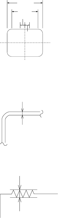
3) Limitation on components depending on the recognition method
(A) Side recognition
Recognition conditions:
① Components whose whole shape is a rectangle or regular square
② Components whose linear portion (line segment) of a side is 1/2 or more of
the component outline size but whose linear portion (line segment) should
be 3 mm or more
③ Components whose side middle section is straight: 1.5 cm on both sides of
the center.
1.5 mm
1.5 mm
Line
segment
Component
outline size
④ Components whose component angle is within 90° ± 0.5°.
⑤ Components whose sides are 0.3 mm or more when their insides are
imaged darkly at imaging
0.3mm or more
⑥ Components whose side roughness forming a linear portion is 0.1 mm or
less
0.1mm or less
⑦ Components whose component shape is not convex.
When the above conditions are satisfied, side recognition is enabled.
Fig. 5.2.3.11-1 Explanatory Drawing of
Recognition Conditions 1), 2) and 3)
Fig. 5.2.3.11-2 Explanatory Drawing of
Recognition Condition 5)
Fig. 5.2.3.11-3 Explanatory Drawing of
Recognition Condition 6)
5 − 23
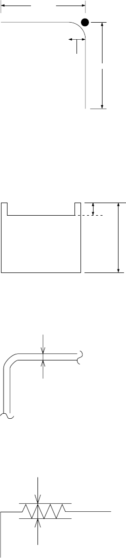
(B) Corner recognition
Recognition conditions:
① Components whose whole shape is a regular square or rectangle
② Components whose corner angle R is 0.5 mm or less
③ Components whose linear portion length forming each side is 2 mm or more
2.00 mm
2.00 mm
0.5 mm
④ Components whose 4 corner points are at vertexes of a regular square or
rectangle
⑤ Components whose outline is not convex
⑥ Components with concave portions whose L1 is 10% or less of L2
L2
L1
⑦ Components whose sides are 0.3 mm or more when their insides are
imaged darkly at imaging
0.3mm or more
⑧ Components whose side roughness forming a linear portion is 0.1 mm or
less
0.1mm or less
♦ When the above recognition conditions are satisfied, corner recognition is
enabled.
Fig. 5.2.3.11-7 Explanatory Drawing of
Recognition Condition 8)
Fig. 5.2.3.11-6 Explanatory Drawing of
Recognition Condition 7)
Fig. 5-2.3.11-5 Explanatory Drawing of
Recognition Condition 6)
Fig. 5.2.3.11-4 Explanatory Drawing of
Recognition Conditions 2) and 3)