KE2040 Instruction Manual_ver1.30.pdf - 第737页
11 − 1 CHA PTER 11 SELF CA LIBRA TION 11.1 Overv iew The item s set f or self -calibrat ion are shown in T able below: Note that a per son who can set the following item s is restrict ed as described under Section 1 1.2 …
10 − 29
10.5.2 Event View buttons
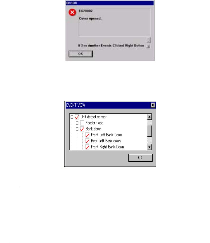
The following screen appears if you open the safety cover, if you press the
Emergency Stop button, or if the machine detects an alarm of each axis servo driver.
◇ The message “If See Another Events Click Right Button” may appears on the
screen. This message appears if two or more events occur at the same time,
and the machine can display the event whose priority is higher only on the screen.
Figure 10.5.2.1 “ERROR” screen
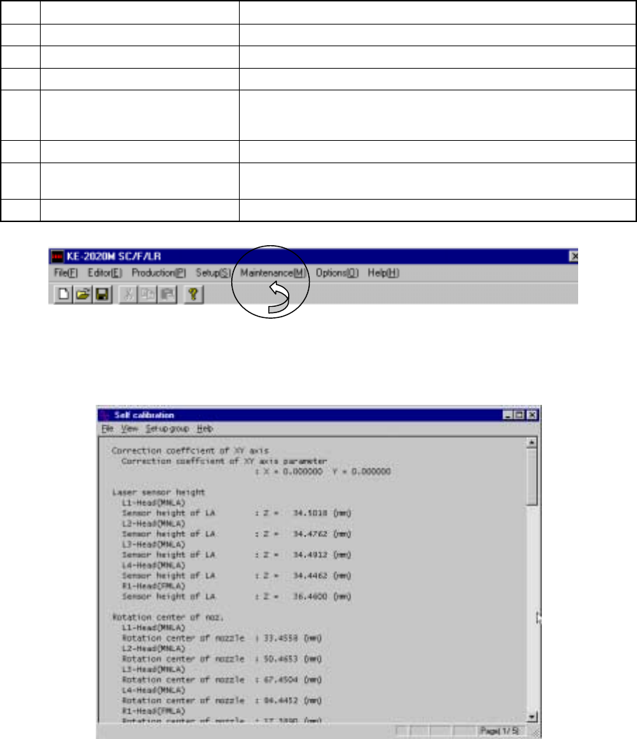
When you click the <OK> button, events are displayed in the hierarchical view.
A check mark is displayed next to the events that actually occurred.
Figure 10.5.2.2 Hierarchical display of events
You do not have to check the events on the hierarchical display above normally.
However, if a driver error occurs and you judges the machine malfunctions, check this
display.
If a driver alarm error appears on the screen, check to see if an event that turns off
the servo power supply (such as Emergency Stop, area sensor activation, feeder float
and so on) occurs. If an event that turns off the servo power supply occurs even
though a driver alarm error appears on the screen, a driver may not malfunction in
many cases.
11 − 1
CHAPTER 11 SELF CALIBRATION
11.1 Overview
The items set for self-calibration are shown in Table below:
Note that a person who can set the following items is restricted as described under
Section 11.2 "User Group Setting".
Before you register the user group, be sure to contact our Technical Service
department.
Table 11.1.1 Self-calibration Items
No. Self-calibration group Description
1 Correct coefficient of XY axis Correction parameter for the XY axes stop accuracy
2 Laser sensor height Height of the laser sensor viewed from the top of a board
3 Rotation center of noz. Center of the nozzle rotation detected with the laser sensor
4 Head offset Assembling position of each head relative to the OCC
Assembling angle of the laser alignment unit relative to the main
unit
5 VCS offset VCS camera assembling position
6 VCS binary-coded threshold
level
Binary-coded threshold when recognized by the VCS (threshold
level)
7 Vacuum calibration Vacuum calibration value
(1) Screen displayed immediately after start-up
When you select the [Self-calibration] command on the [Setup] menu, the
following ”Self calibration” initial screen appears.
Figure 11.1.1 Self calibration initial screen
(Screen example when a KE-2030 is used)
11 − 2
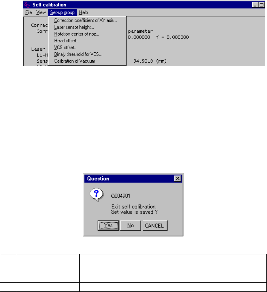
(2) Commands
When you select one of the items displayed above, the corresponding dialog box
appears on the screen.
●
Set-up group
If a unit is not checked on the "Option" menu provided by the MS parameters
(that is, not installed), you cannot select it.
Figure 11.1.2 Set-up group items
(3) Saving the settings
The <OK> button and the <CANCEL> button are provided on each dialog box.
Even though you click the <OK> button, your setting is not at this point.
When you select the [File] command on the menu bar, then the [Exiting
Application] command on the File menu, the Save confirmation dialog box
appears on the screen. When you click the <Yes> button on this dialog box,
your setting is saved.
No. Button you can click Action
1 Yes Saves the settings, then exits from Self-calibration mode.
2 No Cancels your settings, then exits from Self-calibration mode.
3 Cancel Cancels the [Exiting Application] command.