KE2040 Instruction Manual_ver1.30.pdf - 第799页
13 − 17 4. Operati on (1) T eaching Fix the IC collection belt on the f eeder bank , and teach the coor dinates of the IC collection belt position which is selected on the Machine setup menu. Teaching posit ion Figure 13…
13 − 16
This unit allows the machine to collect components which are not placed on a board for
some reason without damaging them after the components are recognized with the
VCS.
Components which are placed on the component sensor ① from the head are fed
sequentially at the pitch selected with the rotary switch ③.
When the belt is full of components and the Stop sensor ② detects a component, the
main unit pauses and displays the message on the screen.
CAUTION
To avoid a risk of injury and prevent the machine from being damaged,
be sure to collect components only after detaching the IC collection belt
from the feeder bank or after you check to see if the machine stops
completely.
If you are to collect components from the IC collection belt being fixed
on the feeder bank, be sure to check to see if there is no person who
may start the machine unexpectedly.
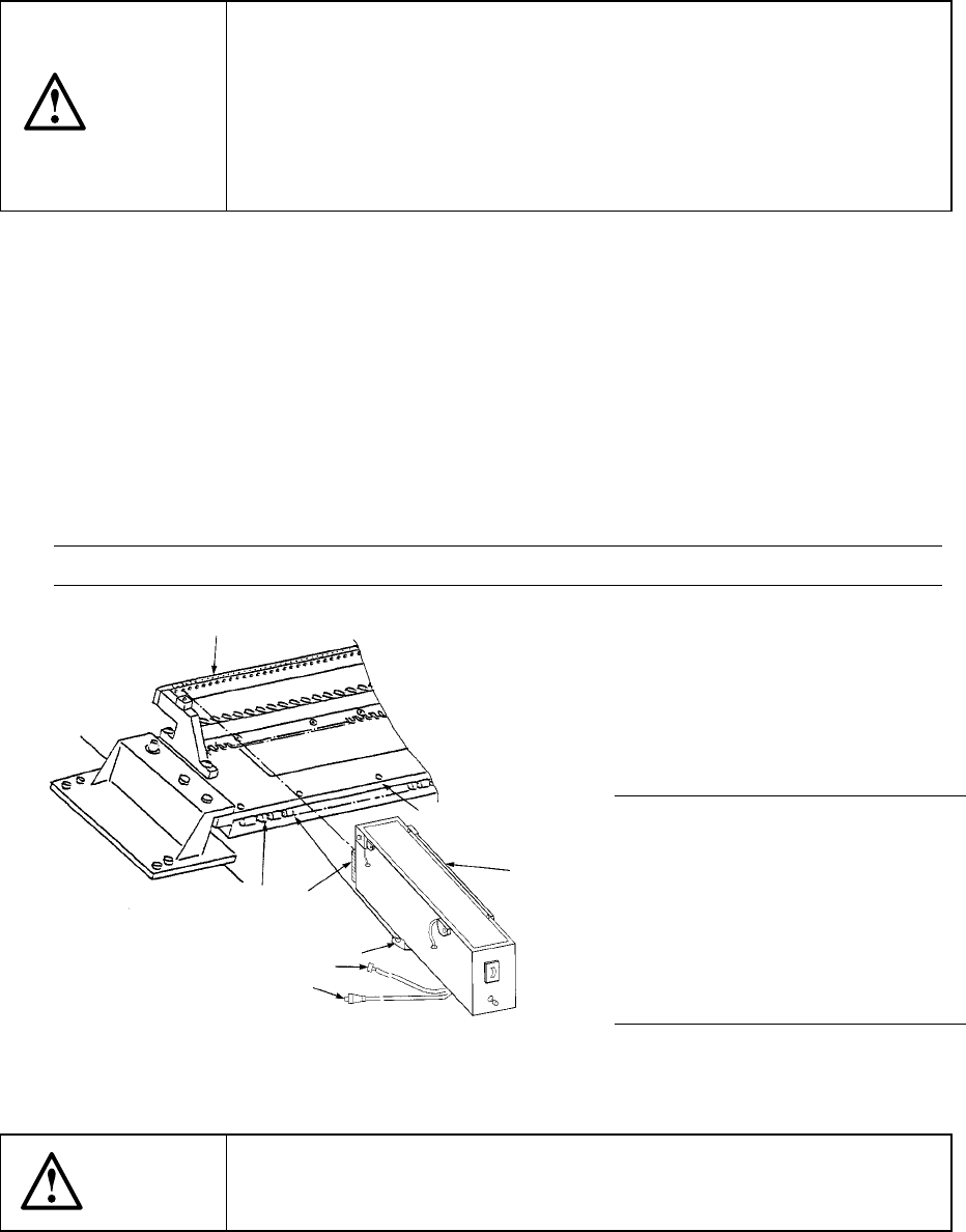
3 Attaching and detaching the IC collection belt
(1) Place the bottom of the IC collection belt ① on the feeder bank ②.
(2) Slide the IC collection belt to align the front positioning pin ⑤ of the IC collection
belt with the fixing hole of the fixing plate ③. Align the lock holder ⑦ with the
V-shaped groove of the lock shaft ⑥, then push the lock holder until it becomes
in contact with the fixing plate ③. Connect the power plug ⑧ of the IC
collection belt to the jack ⑨ of the main unit, and the ALARM signal connector
⑩ to the relay cable.
Note: Check to see if the IC collection does not float nor be tilted.
(3) To detach the IC collection belt,
pull the IC collection belt ①
toward the rear while pulling the
lever of the lock holder ⑦ to
detach it.
Figure 12.10.2 Attaching/detaching the IC collection belt
CAUTION
To avoid any accident caused by sudden activation of the machine,
turn off the power.
①
③
②
⑥
⑤
⑦
⑩
⑧
Note: Attach or detach the IC
collection belt on/from the
main unit only after the
machine stops because it
is very dangerous to attach
or detach it in Production
mode or while the X-Y axes
are moving.
13 − 17
4. Operation
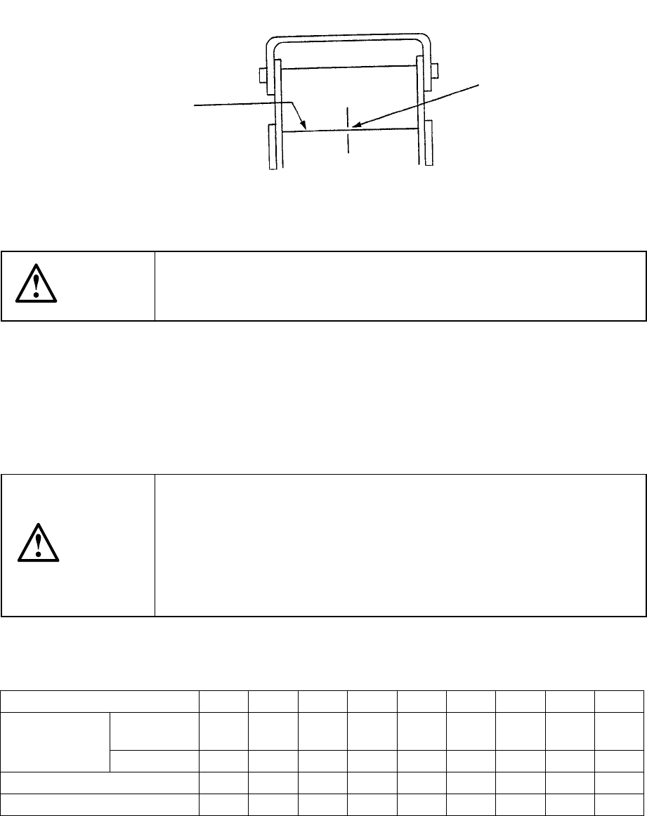
(1) Teaching
Fix the IC collection belt on the feeder bank, and teach the coordinates of the IC
collection belt position which is selected on the Machine setup menu.
Teaching position
Figure 13.10.3 Teaching operation
CAUTION
To avoid a risk of injury, do not place your hand in the machine, nor
move your face or head close to the machine during operation of the
HOD.
(2) Basic operation
The head of the main unit places an IC on the belt, and the component sensor
detects it. After 0.5 seconds, the IC is fed over the belt at the pitch you set. If
the belt gets full of ICs and stops, press the Reset switch to restart the machine
after removing ICs from the belt.
CAUTION
To avoid a risk of injury and prevent the machine from being damaged,
be sure to collect components only after detaching the IC collection belt
from the feeder bank or after you check to see if the machine stops
completely.
If you are to collect components from the IC collection belt being fixed
on the feeder bank, be sure to check to see if there is no person who
may start the machine unexpectedly.
Table 13.10.1 Number of ICs which can be collected
and the feeding pitch set with the rotary switch No.
Switch No. to be set 1 2 3 4 5 6 7 8 9
Equal or
less than
10 15 20 25 30 35 40 45 50 IC size (mm)
Over − 10 15 20 25 30 35 40 45
Belt feeding pitch (mm) 15 20 25 30 35 40 45 50 55
Maximum number of ICs 19 14 11 9 8 7 6 6 5
Optical axis
Teach the center of the
belt on the component
sensor optical axis.
13 − 18
13.11 Handling a Gripper Nozzle
This nozzle is designed exclusively for the KE-2000 series of products to pick up
and/or place on a board a component whose top has no picked-up area, and it is
available to laser and vision recognition.
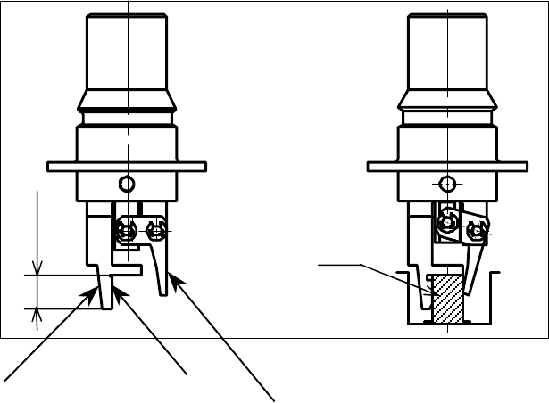
1. Features
The gripper nozzle uses its “fixed arm” and “swing arm” together exclusively to
pick up and/or place a component whose topside has no picked-up area. Its grip
strength is appropriate enough to pick up/place a component stably.
① Fixed arm
② Swing arm
Figure 13.11.1 Name of each part of a nozzle
①
①①
①
②
②②
②
Com
p
onent
Position against a
component is pushed
Length of a lug