KE2040 Instruction Manual_ver1.30.pdf - 第805页
13 − 23 Figure 13.11.6 Setting the l aser height Specify the distance from the tip of a nozz le to the surface on which laser beam impinges. Setting guide: - (component height – 3.5 mm) / 2 Make triv ial adjustments of t…
13 − 22
②
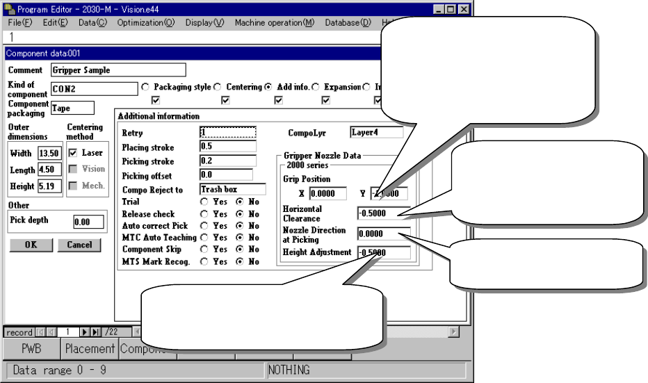
Entering information for controlling a component position picked up by a
gripper nozzle
Figure 13.11.5 Setting the gripper control information
③
Laser pos. (position)
Be careful to enter this setting item when you use a gripper nozzle.
Normally, enter the distance from the top of a component to the surface on
which laser beam impinges in the “Laser pos.” field of a nozzle. However,
when you use a gripper nozzle, enter the distance laser is beamed by
regarding the tip of the nozzle that is located at the fixed arm as a reference
position.
Distance between the fixed arm
and the center of a component
Enter half of the width of the
component-molded part.
(Enter a negative value.)
Clearance between the
fixed arm and the
component molded part
(Enter a negative value.)
Specify the angle of a
nozzle (normally set to 0
A griper nozzle has a dumper. To
hold a component horizontally, enter
about – 0.5 mm as a push-in stroke.
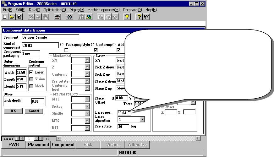
13 − 23
Figure 13.11.6 Setting the laser height
Specify the distance from the tip of a nozzle to the
surface on which laser beam impinges.
Setting guide: - (component height – 3.5 mm) / 2
Make trivial adjustments of this
value according to a lead position.
Example shown on this screen: - (5.19 – 3.5) / 2
= - 0.84
13 − 24
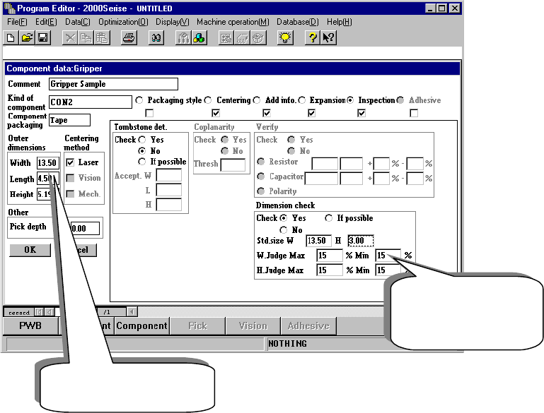
④
Notes on component dimension check
When you specify the “Dimension check” items, be careful to enter the “Std.
Size” (reference size).
◆ The “Std. Size” means the size of the molded part on which laser beam is
to impinge, and it is different from the dimensions of a component
including a lead.
Figure 13.11.7 Setting the “Dimension check” items
Length of a component
including a lead
Length of the molded
part on which laser
beam impinges.