KE2040 Instruction Manual_ver1.30.pdf - 第812页
13 − 30 13.12.2.3 Evaluati on cri teria ■ Colinearity check T he device checks how much leads on each side are bent in the up/ down direction based on the value that is entered to t he menu item “Toler ance” displayed on…
13 − 29
◆ Method specified by EIAJ (default)
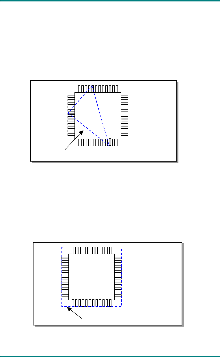
In the geometric plane passing the bottom points of optional three terminals,
all the bottom points of the other terminals exist on the package side and the
center of gravity of the package is included within or on the triangle
comprised of these three points. When the plane satisfies the above
condition and has no effect of the empty weight, it is defined as coplanarity.
In case there are multiple combinations that satisfy the above condition,
adopt a combination in which the coplanarity value becomes large.
Fig. 13-12-2-2 Calculation of Coplanarity by EIAJ
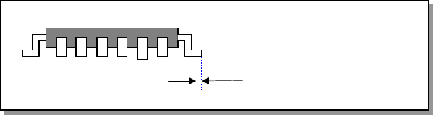
◆ Coplanarity in the method of least squares
In the method of least squares, when the plane obtained by the method of
least squares from the bottom points of all the terminals is in contact with the
bottom point of the most distant terminal from the package side, the distance
up to the most distant terminal is defined as coplanarity.
Fig. 13
Fig. 13-12-2-3 Calculation of Coplanarity by the Method of Least Squares
Plane obtained by the lowest points
Plane obtained by the method
of least squares
13 − 30
13.12.2.3 Evaluation criteria
■ Colinearity check
The device checks how much leads on each side are bent in the up/down
direction based on the value that is entered to the menu item “Tolerance”
displayed on the “COPLA CHECK DATA” dialog box invoked from the Vision data
screen.
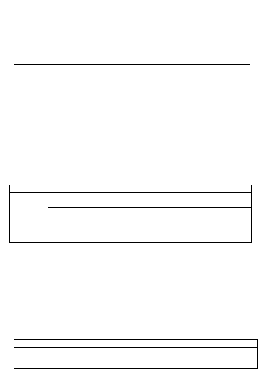
◇ The position to be checked can be set with the menu item “Scanning Offset” on
the Vision data editing screen.
Figure 13.12.2.4 Explanation of the scanning position offset
■ Coplanarity check
The device checks how much a lead is bent in the up/down directions based on
the value that is entered to the menu item “Tolerance” displayed on the “COPLA
CHECK DATA” dialog box invoked from the Vision data screen.
Scanning position offset
13 − 31
13.12.3 Overview of the specifications
(1) Applicable components
QFP and SOP
Only if they are recognized by the VCS.
(2) Resolution and precision
①
Resolution: 1μm
②
Precision: ±20 μm (when measured with a JUKI standard gauge)
L
This device may not correctly judge a component whose terminal is
damaged due to contact with contact probe.
(3) Measurement mode and dimensions of a component
Two measurement modes are provided: Standard mode and High-Precision
mode.
In Standard mode, the device scans a component at 80 mm/s with the sensor,
while in High-Precision mode, it scans a component at 20 mm/s.
◇ Specifications of a component that can be measured in each mode are
shown below:
Table 13.12.1 Dimensions of a component in each mode
Item Standard mode High-Precision mode
Pitch 0.4 mm or more 0.3 mm or more
Lead width 0.18 mm or more 0.12 mm or more
Lead length 0.3 mm or more 0.3 mm or more
Batch
measurement
26 mm x 100 mm or less 26 mm x 50 mm or less
Lead
components
Component
size
Division
measurement
50 mm x 100 mm or less 50 mm x 50 mm or less
◆
When you switch a measurement mode between Standard mode and
High-Precision mode, it takes three seconds to switch the rotating
speed of the polygon mirror. Therefore, if you are to produce both
components that should be measured in Standard mode and those
that should be in High-Precision mode, the production cycle time
becomes longer.
◆
The length of a gull-wing lead indicates that of a lead located on the
foot section.
◆
Component height
* [If the dimensions of a component exceed those above, the
maximum component height should be 8 mm.]
Model name KE-2020 KE-2040
Component height (Maximum) 12mm 20mm 25mm
Note that the value described above is applied to a component when its longer side is 50 mm or shorter, and
the shorter side is 45 mm or shorter.
L