00198371-01_UM_SWS-EN.pdf - 第102页
5 SWS tasks User manual SIPLACE Wafer System (SWS) 5.9 Controls and displays Edition 04/2018 102 5.9.3 Ergonomic arrange ment of controls Fig. 5.9 - 1 , page 100 provides an overview of the posit ion of the c ontrols. Th…
User manual SIPLACE Wafer System (SWS) 5 SWS tasks
Edition 04/2018 5.9 Controls and displays
101
5.9.2 Description
All the controls can be reached by a 1.40 m tall person.
Main switch
The main switch is used for switching the power supply to the SWS on and off.
5
EMERGENCY STOP button
The EMERGENCY STOP button latches in the ON position when pressed. The power supply will
be interrupted. Turn the button to release it.
LCD touchscreen
Each SWS features a flat screen monitor with LCD technology and touchscreen function for op-
eration of the SWS software.
Keyboard
The keyboard is located beneath the monitor.
5
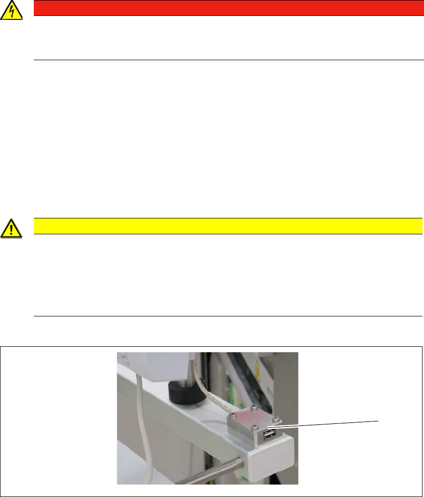
USB connection
5
Fig. 5.9 - 2 USB connection
There is a USB connection next to the LCD screen (1).
DANGER
Lethal voltages!
Some parts inside the SWS carry potentially lethal voltages - even when switched off at
the main power switch.
CAUTION
Risk of collision on the monitor with keyboard
When working on the SWS, there is risk that you could collide with the monitor and key-
board.
Turn the monitor and keyboard away to the side.
Make sure that you are not under the monitor and keyboard with your head.
(1)

5 SWS tasks User manual SIPLACE Wafer System (SWS)
5.9 Controls and displays Edition 04/2018
102
5.9.3 Ergonomic arrangement of controls
Fig. 5.9 - 1, page 100 provides an overview of the position of the controls. They are subdivided
into the following groups:
– LCD touchscreen
– Keyboard
– EMERGENCY STOP button
– Main switch
5.9.3.1 Controls on the control panels
The two operator panel have identical control functions.
Monitor and keyboard,
The SIPLACE Wafer System has a monitor and keyboard attached.
Main switch
The main power switch is part of the power module. It is located here because it is only needed
for servicing and preventive maintenance work and is therefore not subject to frequent use.
User manual SIPLACE Wafer System (SWS) 5 SWS tasks
Edition 04/2018 5.10 Switching on and off
103
5.10 Switching on and off
5.10.1 Switching the SWS on
First switch on all existing SWS modules for the SIPLACE CA4 V2.
The modules are starting up. As long as the placement machine is not yet switched on, an
error message will be displayed on the screen of the SWS module, which points out that
the safety circuit is not closed. 5
Switch the placement machine on.
The station computer will start. 5
As soon as the placement machine has been started up and the start button has been pressed,
the error message regarding the not-closed safety circuit vanishes from the SWS monitors. Initial-
ize the SWS module.
When the initializing process is completed, the SWSs are ready to operate and in standby.
5.10.2 Switching the SWS off
Switching off the SWS
Complete all processes running at the SWS modules.
Select Settings -> Shut down machine.
SWS GUI and Linux are shut down properly. 5
Switch off the SWS at the main switch.
Repeat this, if necessary, for each other SWS module.