00198371-01_UM_SWS-EN.pdf - 第126页
6 Options User manual SIPLACE Wafer System (SWS) 6.3 SWS wafer stretcher (expander) Edition 04/2018 126 Dismantling the sensors for the 8" stroke ring The two sensors are fixed to the stroke ring in the 8" wafe…
User manual SIPLACE Wafer System (SWS) 6 Options
Edition 04/2018 6.3 SWS wafer stretcher (expander)
125
Removing the stroke ring
You need to replace the stroke ring for the relevant wafer support.
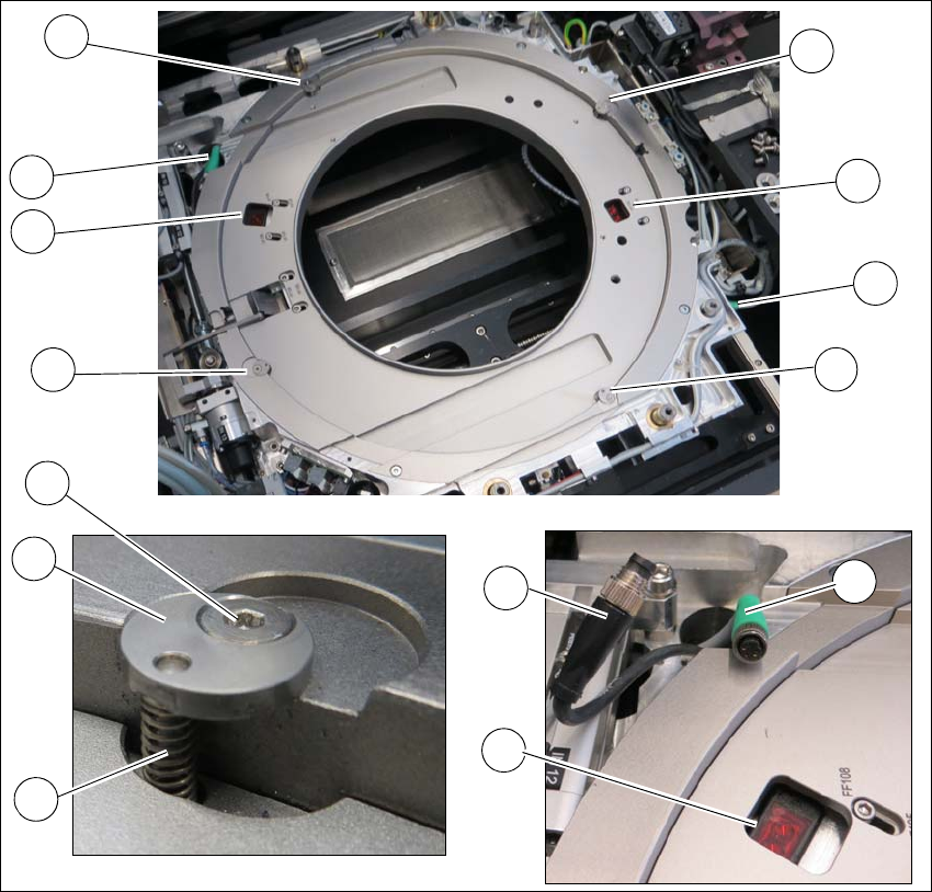
Fig. 6.3 - 9 Wafer support - removing the stroke ring
Loosen the 4 screws (1) fixing the stroke ring.
Remove the fixing disc (2) and the spring (3). Make sure that the fixing disc (2) and the spring
(3) are kept safe for refitting later on.
Unplug the two sensors (4) from the connector (5) of the cable extension (6).
Remove the stroke ring.
1
1
1
2
3
1
4
4
5
4
5
1
5
6
6 Options User manual SIPLACE Wafer System (SWS)
6.3 SWS wafer stretcher (expander) Edition 04/2018
126
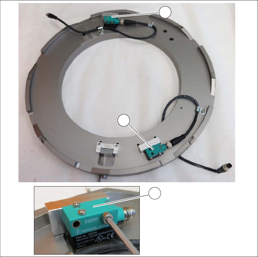
Dismantling the sensors for the 8" stroke ring
The two sensors are fixed to the stroke ring in the 8" wafer support. These sensors need to be
dismantled for later refitting of the 8" stroke ring. In the case of the 12" wafer support, both sensors
are fitted to the wafer support in the SWS, using the brackets supplied.
6
Fig. 6.3 - 10 Wafer support - 8" stroke ring removed
Dismantle the heat protection plates fitted over the sensors.
Dismantle the two sensors (1) from the assembly brackets of the stroke ring.
Remove the two sensors and fit these on the two assembly brackets from the 12" retrofit kit.
1
1
1
User manual SIPLACE Wafer System (SWS) 6 Options
Edition 04/2018 6.3 SWS wafer stretcher (expander)
127
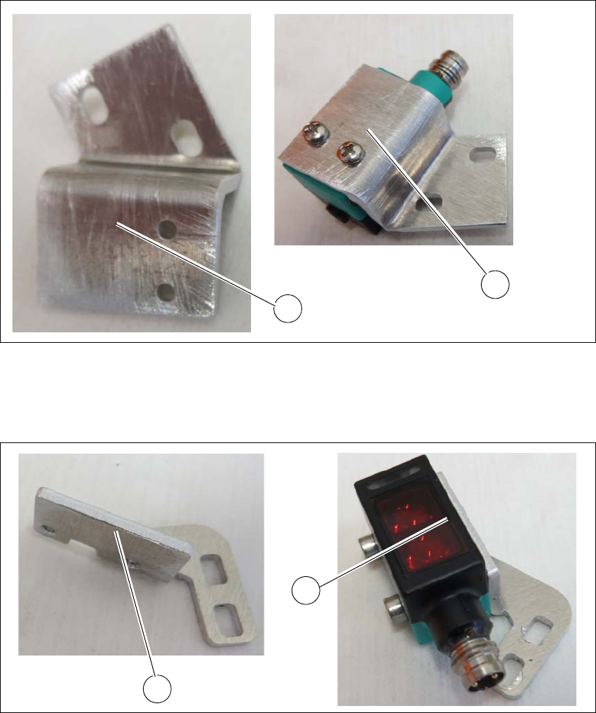
Fitting the sensors on the assembly brackets for the 12"
6
Fig. 6.3 - 11 Wafer support - sensor 1
(1) Assembly bracket
(2) Sensor fitted to assembly bracket
6
Fig. 6.3 - 12 Wafer support - sensor 2
(1) Assembly bracket
(2) Sensor fitted to assembly bracket
Fit the two sensors (2) to the assembly bracket (1) from the 12" retrofit kit.
1
2
1
2