00198371-01_UM_SWS-EN.pdf - 第19页
User manual SIPLACE Wafer System (SWS) 1 Introduction Edition 04/2018 1.2 Description of functions 19 1.2.3.1 Flip chip process The flip chip process is the st andard method for SWS. The die is rot ated by 180° before pl…
1 Introduction User manual SIPLACE Wafer System (SWS)
1.2 Description of functions Edition 04/2018
18
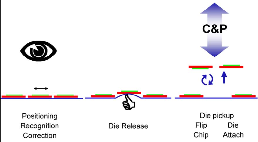
1.2.3 Basic die presentation process
The basic die presentation process supported by the SWS can be divided into 3 main steps:
– Die recognition and positioning for ejection (inc. inkspot recognition)
– Ejection process
– Die attach or flip chip process.
1
Fig. 1.2 - 1 Basic die presentation process (basic principle)
There are two main ways to process dies:
– Flip chip process
– Die attach process
User manual SIPLACE Wafer System (SWS) 1 Introduction
Edition 04/2018 1.2 Description of functions
19
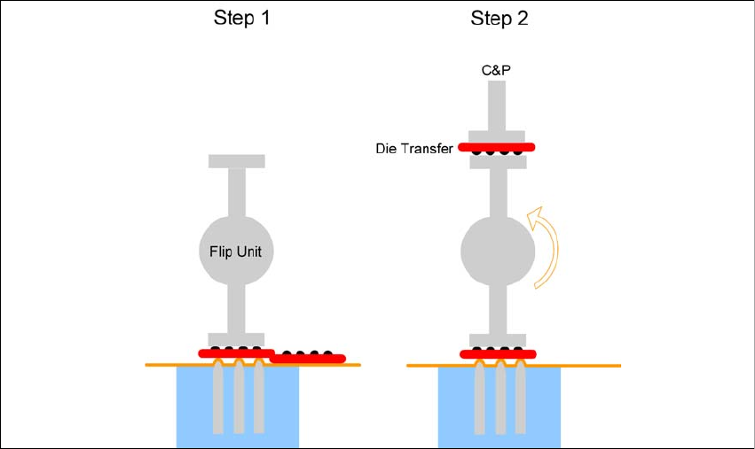
1.2.3.1 Flip chip process
The flip chip process is the standard method for SWS. The die is rotated by 180° before placement
(face down placement).
1
Fig. 1.2 - 2 Flip chip process (basic principle)
The flip chip process steps are:
– Step 1: Die release
– Step 2: The die is rotated by 180° and is passed on to the placement head. Parallel to this,
the next die is taken up by the second nozzle of the flip unit.
1 Introduction User manual SIPLACE Wafer System (SWS)
1.2 Description of functions Edition 04/2018
20
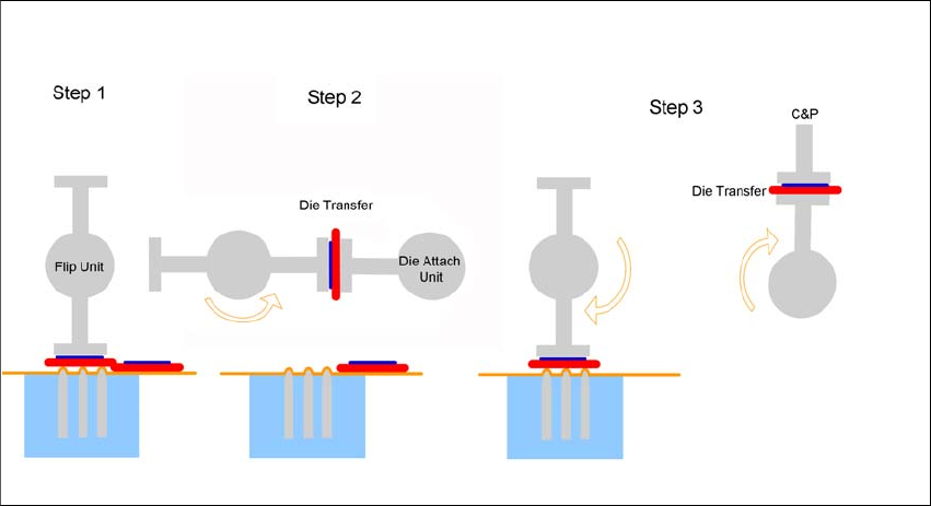
1.2.3.2 Die attach process
The optional die attach unit is needed for the die attach process.
In this method, the die is placed in the same bottom/top orientation as it was on the wafer foil
("face-up" placement).
1
Fig. 1.2 - 3 Die attach process steps (basic principle)
The die attach process steps are:
– Step 1: Die release
– Step 2: The die is rotated by approx. 130°and transferred to the die attach unit.
– Step 3: The die attach unit rotates the die into the pickup position and transfers it to the place-
ment head. Parallel to this, the next die is picked up by the flip unit.