00198371-01_UM_SWS-EN.pdf - 第52页
2 Operational safety User manual SIPLACE Wafer System (SWS) 2.6 Safety features Edition 04/2018 52 EMERGENCY STOP button with forced locking The EMERGENCY STOP button is red and lat ches in the ON position when pressed. …
User manual SIPLACE Wafer System (SWS) 2 Operational safety
Edition 04/2018 2.6 Safety features
51
Function
If the SWS sliding door is opened upwards, the power supply for the SWS lift and the gripper will
be interrupted. A message is issued on the screen, notifying you that the sliding door has been
opened.
2.6.2 EMERGENCY STOP button and main switch
2
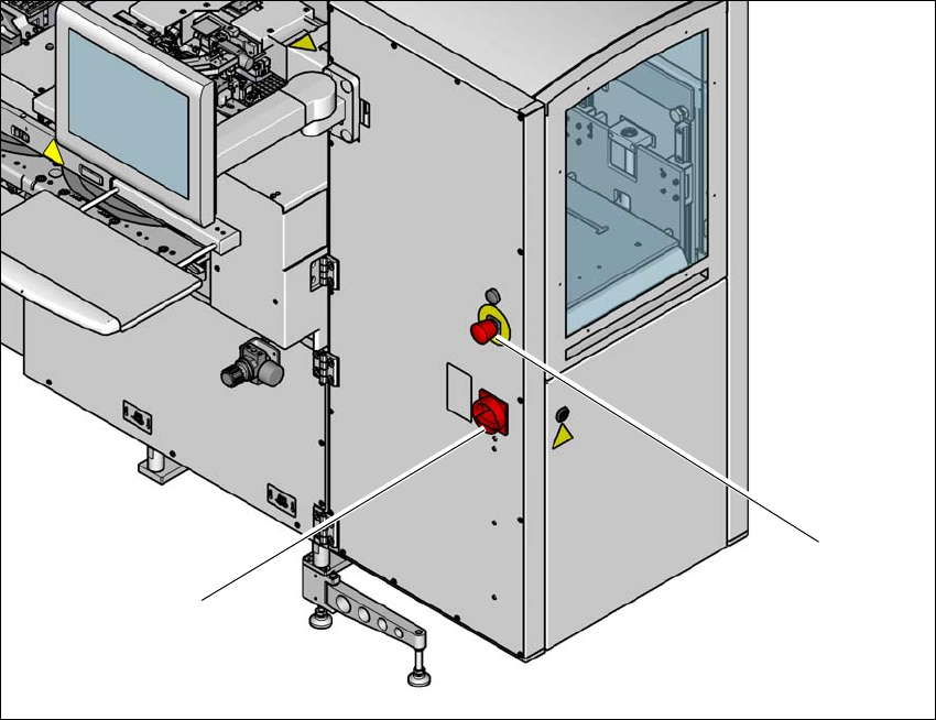
Fig. 2.6 - 2 Position of EMERGENCY STOP button and main switch on the SWS
(1) EMERGENCY STOP button
(2) Main switch
(1)
(2)

2 Operational safety User manual SIPLACE Wafer System (SWS)
2.6 Safety features Edition 04/2018
52
EMERGENCY STOP button with forced locking
The EMERGENCY STOP button is red and latches in the ON position when pressed. Pressing
the EMERGENCY STOP button triggers the safety cutoff (see also section 2.6.3
, page 53).
The operating status indicator (white) is switched off.
Main power switch in the OFF position
2
Main switch in ON position
After you switch on using the main switch, the SIPLACE Wafer System computer will boot.
Position switch, SWS sliding door
The position switch checks whether the SWS sliding door is open or closed. The position switch
on the SWS sliding door triggers the safety cutoff (lock) when the SWS sliding door is opened.
Individual components are disabled or remain enabled
DANGER
Lethal voltages!
Incorrect handling of the SIPLACE Wafer System can therefore result in death or severe
injury or considerable damage to equipment.
Some parts of the SIPLACE Wafer System carry potentially lethal voltages, even when it
is switched off at the main power switch:
Always follow the applicable accident prevention and DIN regulations (particularly EN
60204, part 1 or IEC 60204, part 1) and the applicable regulations in your own coun-
try.
The safety door to the power supply must ONLY be opened by appropriately qualified
and trained personnel.
User manual SIPLACE Wafer System (SWS) 2 Operational safety
Edition 04/2018 2.6 Safety features
53
2.6.3 Safety cutoff
The SIPLACE Wafer System (SWS) safety cutoff is locked with the SIPLACE CA4 V2 so that the
SIPLACE Wafer System is only active if the safety cutoff (CSB) for the SIPLACE CA4 V2 is en-
abled.
When pressed, the EMERGENCY STOP button on the SIPLACE Wafer System affects the safety
cutoff (CSB) for the SIPLACE CA4 V2 by triggering the emergency stop function of the SIPLACE
CA4 V2 and also the emergency stop function of the SIPLACE Wafer System via its own safety
cutoff.
2.6.3.1 Prerequisites
The following conditions must be fulfilled in order to start and operate the SWS with the SIPLACE
CA4 V2:
– All component trolleys must be docked into place.
– The SIPLACE Wafer System modules must be fitted and connected (interface connector
X1*3).
– The sliding door of the installed SIPLACE Wafer System modules must be closed.
– All protective covers on the SIPLACE CA4 V2 must be closed.
– All side sliding doors on the SIPLACE CA4 V2 must be closed.
– The two EMERGENCY STOP buttons on the SIPLACE CA4 V2 and the SIPLACE Wafer Sys-
tem (one EMERGENCY STOP button per SWS) must be released.
– The minimum operating pressure must have been reached.
– The software release ("Control ON") must be enabled.
If one of the start buttons is now pressed, the safety cutoff (CBS) will switch the supply voltage on.
The SWS and the SIPLACE CA4 V2 will be ready for operation.
2.6.3.2 Safety cutoff components
The following components are monitored by the safety cutoff:
– Position switch of the four protective covers on the SIPLACE CA4 V2
– Position switch of the four side sliding doors on the SIPLACE CA4 V2
– Position switch for the sliding door on the SIPLACE Wafer System (SWS)
– Two EMERGENCY STOP buttons on the SIPLACE CA4 V2
– EMERGENCY STOP button on the SIPLACE Wafer System (SWS)
– Position switch on the COT inserts of the SIPLACE CA4 V2