00198371-01_UM_SWS-EN.pdf - 第55页
User manual SIPLACE Wafer System (SWS) 2 Operational safety Edition 04/2018 2.6 Safety features 55 2.6.4 Energy st ate of the SWS after s witching off at the main power switch 2 2 2.6.5 Compressed air conditions in the S…
2 Operational safety User manual SIPLACE Wafer System (SWS)
2.6 Safety features Edition 04/2018
54
2.6.3.3 Enabling the EMERGENCY STOP
If problems occur, the SIPLACE Wafer System (SWS) can be stopped by pressing the EMER-
GENCY STOP button.
An EMERGENCY STOP can be triggered by:
– Pressing the EMERGENCY STOP button on the SIPLACE Wafer System (SWS)
– Pressing an EMERGENCY STOP button on the SIPLACE CA4 V2
In these cases, the safety cutoffs of the SIPLACE CA4 V2 and SIPLACE Wafer System are trig-
gered and the power contactor is switched off within 100 ms or 500 ms (STOP category 1, con-
trolled shutdown with interruption of energy supply at standstill).
2.6.3.4 Resetting an EMERGENCY STOP
To reset an EMERGENCY STOP, make sure that the EMERGENCY STOP buttons for the SI-
PLACE CA4 V2 and the SIPLACE Wafer System (SWS) are unlocked.
Find out the reason why the EMERGENCY STOP button triggered.
Remove the cause.
Unlock the relevant EMERGENCY STOP button for the SIPLACE CA4 V2 or the
SIPLACE Wafer System (SWS).
2.6.3.5 Resetting the lock
Close any open protective covers/sliding doors on the SIPLACE CA4 V2.
Close the open sliding door on the SIPLACE Wafer System (SWS).
2.6.3.6 Triggering the lock
Open a protective cover/sliding door on the SIPLACE CA4 V2.
Open the sliding door on the SIPLACE Wafer System (SWS).
User manual SIPLACE Wafer System (SWS) 2 Operational safety
Edition 04/2018 2.6 Safety features
55
2.6.4 Energy state of the SWS after switching off at the main power switch
2
2
2.6.5 Compressed air conditions in the SWS after switching off at the main power
switch
When switching off the main switch or if the power supply fails, the electrically-controlled main
valve of the compressed air unit will close. The pressure will drop to 0 MPa (0 bar) within 5 sec-
onds.
CAUTION
Please note that each SIPLACE Wafer System has its own main switch.
DANGER
Lethal voltages in the power supply unit!
The power supply unit has certain components (such as the mains power filter) which still
conduct lethal voltages even when it is switched off.
Only ASM Assembly Systems GmbH&Co.KG service engineers or the machine
owner's service engineers, who have been trained by ASM, may perform work on the
power supply and the safety cutoff (CBS).
CAUTION
Data loss!
To avoid data loss, only switch the SIPLACE Wafer System off after fulfilling the following
criteria (unless it is an emergency):
– The SIPLACE Wafer System has completed data transfer.
– The SIPLACE Wafer System has completed processing.
– The SIPLACE Wafer System has completed the shutdown phase.
2 Operational safety User manual SIPLACE Wafer System (SWS)
2.7 Disabling the compressed air supply and discharging the pressure Edition 04/2018
56
2.7 Disabling the compressed air supply and discharging
the pressure
The compressed air unit is located on the back of the SWS (see fig. 2.7 - 1, page 56 ). The com-
pressed air working pressure of the SWS is set to 0.50 ± 0.025 MPa (5.0 ± 0.25 bar).
2
2
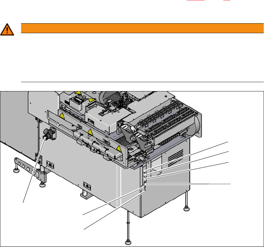
Fig. 2.7 - 1 Electrical and pneumatic connection point on the SWS (example SWS 2/4)
2
WARNING
Risk of injuries!
Risk of injuries from pressurized compressed air lines. The compressed air supply to the
SWS is made available by the SIPLACE CA4 V2.
Switch the compressed air off at the SIPLACE CA4 V2.
NEVER detach compressed air lines while they are still pressurized.
(1) Setting the air blast for flip head segments
or die attach segments
(2) Voltage supply
(3) Interface safety cutoff with SIPLACE CA4
V2
(4) CAN bus (for SW 605.x only)
(5) Opening for compressed air hose from the
SIPLACE CA4 V2
(6) LAN1 - communication with external map
server
(7) LAN2 - communication with SIPLACE CA4
V2 and possible with other SWS
(1)
(2)
(3)
(4)
(6)
(7)
(5)