00198371-01_UM_SWS-EN.pdf - 第61页
User manual SIPLACE Wafer System (SWS) 3 Technical data and assemblies Edition 04/2018 3.1 Technical data - SWS 61 3 T echnical dat a and assemblies 3.1 T echnical dat a - SWS 3 T echnical data Flip chip Die att a ch Min…

2 Operational safety User manual SIPLACE Wafer System (SWS)
2.9 ESD guidelines Edition 04/2018
60
2.9 ESD guidelines
2.9.1 What does ESD mean?
Almost all of the modules in use today are equipped with highly integrated MOS blocks and com-
ponents. The manufacturing techniques used mean that these electronic components are ex-
tremely sensitive to overvoltage and thus to electrostatic discharge.
The abbreviation for such modules is 'ESD' (Electrostatic Sensitive Device). ’ESD’ is used inter-
nationally. The following symbol on cabinet typeplates, racks or packaging indicates that compo-
nents which are sensitive to electrostatic discharge have been used and that the modules
concerned are also touch-sensitive.
ESDs can be destroyed by voltages and power levels that are far below the level
that can be perceived by humans. Such voltages occur if a person touches a com-
ponent or module without earthing themselves. Components that are exposed to
such overvoltages do not generally appear to be defective immediately - incorrect
behavior starts after the component or module has been in operation for some time.
2.9.2 Important measures to protect against static charging
Most plastics can easily become charged and must therefore be kept away from at-risk com-
ponents.
Always ensure that people, the workplace and packaging are safely earthed when handling
electrostatic sensitive components.
User manual SIPLACE Wafer System (SWS) 3 Technical data and assemblies
Edition 04/2018 3.1 Technical data - SWS
61
3 Technical data and assemblies
3.1 Technical data - SWS
3
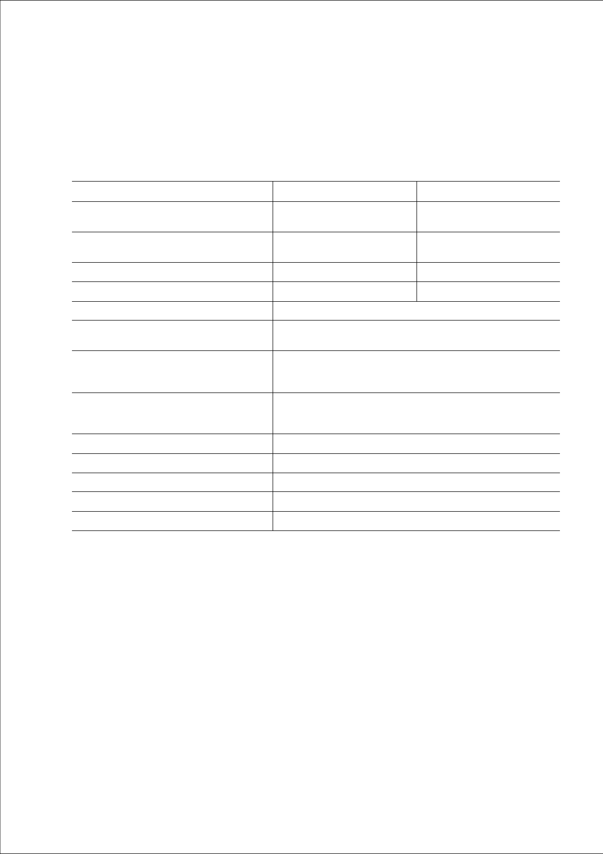
Technical data Flip chip Die attach
Minimum die thickness (silicium) - without com-
ponent sensor
50 µm 50 µm
Minimum die thickness (silicium) - with compo-
nent sensor
100 µm 100 µm
Minimum bump size 50 µm n/a
Minimum bump grid 100 µm n/a
SIPLACE Wafer System SWS Horizontal system, automatic wafer change, MCM
SWS wafer size 4" to 12"
4" / 6" with adapter on request
Wafer frame 12“/8“
6" on request
4" with adapter
Wafer frame:Maximum height 12": 8.1 mm
8": 7.6 mm
6": 5.8 mm
Wafer magazine
*a
Up to 12"
Die Ejection System Programmable ejection speed (synchronous and asynchronous)
Option: Linear Dipping Unit LDU Freely programmable speed
Flux viscosity 3,000 to 100,000 cPs
Accuracy of flux height ± 5 µm
*)a Depending on the wafer magazine, you may need to mechanically adjust the base plate for the wafer magazines.

3 Technical data and assemblies User manual SIPLACE Wafer System (SWS)
3.2 Ambient conditions and connection values Edition 04/2018
62
3.2 Ambient conditions and connection values
3.2.1 Ambient conditions for packaging, transportation and storage
3
3.2.2 Environmental conditions for operation
3
3.2.3 Electrical ratings and energy consumption
3
3
Temperature range Between -25°C and 55°C
Atmospheric humidity Up to 95%
Ambient pressure Up to 1.700 m height without pressure equalization
Room temperature Between 15°C and 35°C
Atmospheric humidity 30% to 75%
(on average not higher than 45%, so that there is no risk of
condensation on the machine.)
Ambient pressure > 750 mbar (corresponds to 2500 m above mean sea level)
PLEASE NOTE
Use of a residual current protection device
The low ground leakage current of the system makes it possible to use an upstream
residual current protection device at the customer end. This must be all-current sen-
sitive (RCD type B).
Electrical ratings
Supply voltage Fuse
Mains power supply 3 x 380 V~ to 3 x 415 V~ ± 10 %; 50/60 Hz
3 x 200 V~ to 3 x 230 V~ ± 10 %; 50/60 Hz
*a
3 x 16A characteristic C
3 x 16A characteristic C
*b
Mains power con-
nection
Cable 4 x 2.5 mm² with CEKON connector (3 x 380 V~ to 3 x 415 V~)
Cable 4 x 2.5 mm² (3 x 200 V~ to 3 x 230 V)
Energy consumption
With heater Without heater
Nominal apparent power 2.8 kVA 0.8 kVA
Nominal active power 2.6 kW 0.6 kW
*)a With options package
*)b e.g. Siemens circuit breakers in accordance with IEC and UL 489 (order no.: 5SJ4 316-7HG42)
or
EATON Industries circuit breaker FAZ-C16/3-NA 16A 3p (UL 489, CSA C22.2 no. 5, IEC 60947-2)