00198371-01_UM_SWS-EN.pdf - 第73页
User manual SIPLACE Wafer System (SWS) 3 Technical data and assemblies Edition 04/2018 3.4 Description of the SWS modules 73 3.4.4.1 W afer support The wafer support is fitted to the X-Y unit and is ther efore pa rt of t…
3 Technical data and assemblies User manual SIPLACE Wafer System (SWS)
3.4 Description of the SWS modules Edition 04/2018
72
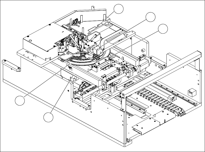
3.4.4 Wafer table
The wafer table consists of an X-Y unit (movement system with 2 linear axes) and the wafer sup-
port.
The wafer table moves the wafer support with the wafer to the required positions in the processing
area.
3
Fig. 3.4 - 3 Wafer table
(1) Clamping unit
(2) Wafer camera
(3) Flip unit
(4) Wafer support
(5) Guidance
4
3
1
2
5
User manual SIPLACE Wafer System (SWS) 3 Technical data and assemblies
Edition 04/2018 3.4 Description of the SWS modules
73
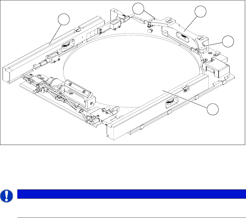
3.4.4.1 Wafer support
The wafer support is fitted to the X-Y unit and is therefore part of the wafer table. The wafers are
fixed to this for the ejection procedure.
3
Fig. 3.4 - 4 Wafer support without wafer inserted (example for 12")
(1) Pin for locking and position detection
(2) Wafer locking bar
3
PLEASE NOTE
To process 8" or 6" wafers, you need to change the wafer support.
6" wafers can be used with the relevant adapters.
1
2
1
2
2
3 Technical data and assemblies User manual SIPLACE Wafer System (SWS)
3.4 Description of the SWS modules Edition 04/2018
74
3
Fig. 3.4 - 5 Wafer support with wafer inserted (example for 12")
(1) Recess for the defined positioning on the pins of the locking bar
(2) Wafer locking bar
(3) Wafer
(4) Rail
3
PLEASE NOTE
Problems recognizing frames during clamping
If the wafer locking bar (2) has been incorrectly attached, the frame will not be recognized
correctly during clamping.
When using 8" wafer supports, make sure that the wafer locking bar (2) is attached in
a manner that allows the pins of the locking bar to engage with the recess on the wa-
fer frame.
3
1
4
2
1