00198371-01_UM_SWS-EN.pdf - 第81页
User manual SIPLACE Wafer System (SWS) 3 Technical data and assemblies Edition 04/2018 3.4 Description of the SWS modules 81 3.4.7.3 W afer changer According to the lo cation (2 and 4 o r 1 and 3) ther e are two differen…
3 Technical data and assemblies User manual SIPLACE Wafer System (SWS)
3.4 Description of the SWS modules Edition 04/2018
80
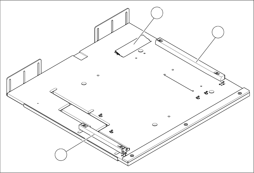
3.4.7.2 Adjustable magazine plate
3
Fig. 3.4 - 10 Adjustable magazine plate
3
The stop bars can be fitted in the relevant positions for 6", 8"or 12" magazines.
(1) Stop bar for fixed assembly position (for 6",
8"or 12 " magazines
(2) Stop bar for variable assembly position (for
6", 8"or 12 " magazines
(3) Magazine recognition
2
1
3
User manual SIPLACE Wafer System (SWS) 3 Technical data and assemblies
Edition 04/2018 3.4 Description of the SWS modules
81
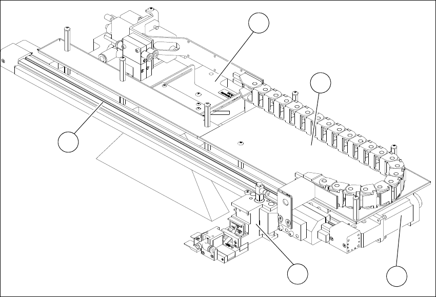
3.4.7.3 Wafer changer
According to the location (2 and 4 or 1 and 3) there are two different versions of the wafer changer.
3
Fig. 3.4 - 11 Main gripper modules (location 2,4)
3
(1) Gripper (2) Toothed belt axis
(3) Installation location for barcode scanner
(optional)
(4) AD-MOT board below the cover
(5) Motor with coupling
1
4
5
3
2
3 Technical data and assemblies User manual SIPLACE Wafer System (SWS)
3.4 Description of the SWS modules Edition 04/2018
82
3
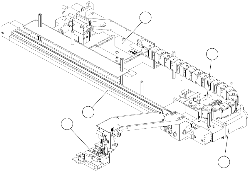
Fig. 3.4 - 12 Main gripper modules (location 1,3)
(1) Gripper (2) Toothed belt axis
(3) Insertion location for barcode scanner
(optional)
(4) AD-MOT board
(5) Motor with coupling
1
2
4
5
3