00198371-01_UM_SWS-EN.pdf - 第86页
4 Setting up and commissioning User m anual SIPLACE Wafer System (SWS) 4.1 Delivery configuration and tr ansportation of SWS Edition 04/2018 86 4.1.3.3 Fork lif t attachment point s on the SWS 4 . 4 Fig. 4.1 - 2 Attachme…
User manual SIPLACE Wafer System (SWS) 4 Setting up and commissioning
Edition 04/2018 4.1 Delivery configuration and transportation of SWS
85
4.1.3 Transporting the SWS without a crate or pallet
4.1.3.1 Safety instructions
4
4
4
4.1.3.2 Means of transport
Use a fork-lift truck or suitable hand lift with the following specification to transport the SIPLACE
Wafer System:
4
4
WARNING
Observe the applicable accident prevention regulations!
The applicable accident prevention regulations concerning the transportation of
heavy goods must be followed.
WARNING
DANGER OF CRUSHING!
Risk of feet being crushed during transportation of the SIPLACE Wafer System.
Wear special protective shoes.
WARNING
Damage to the SIPLACE Wafer System!
If transported without a transportation crate or pallet, the SIPLACE Wafer System could
be damaged.
Read this section through completely before transporting the machine.
Fork length Min. 1600 mm
Lifting power Min. 1500 kg
Outer fork width Min. 450 mm
Max. 520 mm
PLEASE NOTE
Hand lift specifications
The necessary width of the fork lift presents a critical measure.
Make sure that the hand lift used fulfills the specified requirements.
4 Setting up and commissioning User manual SIPLACE Wafer System (SWS)
4.1 Delivery configuration and transportation of SWS Edition 04/2018
86
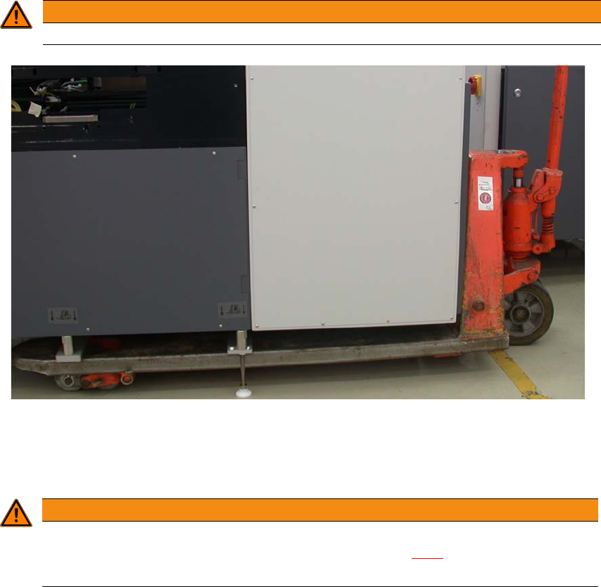
4.1.3.3 Fork lift attachment points on the SWS
4
. 4
Fig. 4.1 - 2 Attachment points for fork-lift or hand lift on SWS
4.1.3.4 Points to be observed while transporting the SWS
4
WARNING
Only lift the SWS by its metal frame.
WARNING
Center of gravity for the SWS
Keep an eye on the SWS center of gravity (see section 3.2.6), particularly when mov-
ing it sideways.
User manual SIPLACE Wafer System (SWS) 4 Setting up and commissioning
Edition 04/2018 4.2 Infrastructure at the installation location
87
4.2 Infrastructure at the installation location
For details, see the user manual for the SIPLACE CA4 V2, German [item no.: 00198381-xx], En-
glish [0198382-xx].
4
4.2.1 Weight and surface load
The machine weight values can be found in section 3.2.5, page 63.
4.2.2 Compressed air supply to SWS
The compressed air supply to the SWS is provided directly from the SIPLACE CA4 V2.
4.2.3 Mains power supply to the SWS
4.2.3.1 Danger notes
4
PLEASE NOTE
Also observe the document "Network and compressed air configuration for SMD sys-
tems" (German+English, item no. 00197548-xx), supplied to you on delivery.
DANGER
Dangerous voltage levels!
The SIPLACE Wafer System is supplied with 3 x 380 V~ to 3 x 415 V ± 10 %, 50/60 Hz
or optionally with 3 x 200 V~ to 3 x 340 V~ ± 10 %; 50/60 Hz mains voltage. This means
that some parts of the system carry potentially lethal voltages - even when switched off at
the main power switch and with disconnected mains plug.
Incorrect handling of the SIPLACE Wafer System can therefore result in death or severe
injury or considerable damage to equipment.
Always follow the applicable accident prevention and DIN regulations (particularly EN
60204, part 1 or IEC 60204, part 1) and the applicable regulations in your own coun-
try.
The covers over the power supply unit may ONLY be opened by appropriately quali-
fied and trained personnel.