OPERATING MANAUAL(FOR ENGINEERS) - 第120页
Page 5-24 T eaching the Chip Recognition 24 . Press Recognition . • Recognition result appears on the recognition screen. ∗ When the recognition result (ANS=) is under the recognition rate (judgment value of machine para…
Page 5-23
TEACHING
5
Teaching the Chip Recognition
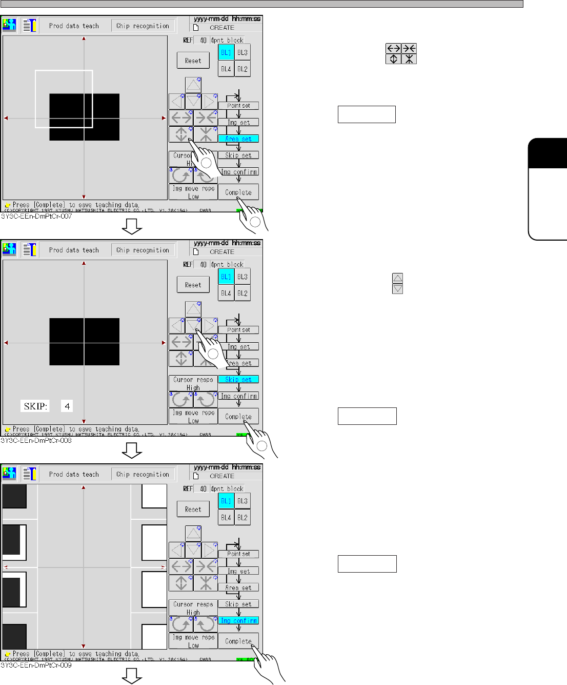
17. Set the area to be recognized by BL 1.
• Set the size with .
Set the size so that the recognition point (set at
procedure 13.) is in the area.
18. Press Complete .
• Data is automatically saved.
19. Repeat the procedure 13 to 18, and
keep setting to BL4.
20. Set the skip value.
• Set the value with .
The image to be recognized is searched
precisely at 1, and roughly at 10, (usually : 4).
Recognition image detection is finally recog-
nized at skip 1.
In recognition, the image is searched at the set
skip value at first, and finally a position is
detected at skip value 1.
21. Press Complete .
• Teaching image for each block appears.
22. Check the taught image.
• Left : position to be recognized (point setting)
Right : Image area to be recognized (image
setting)
23. Press Complete .
• Teaching for each block is finished.
3Y3C-E-EMD05-A01-00
1
2
1
2
To the next page
Page 5-24
Teaching the Chip Recognition
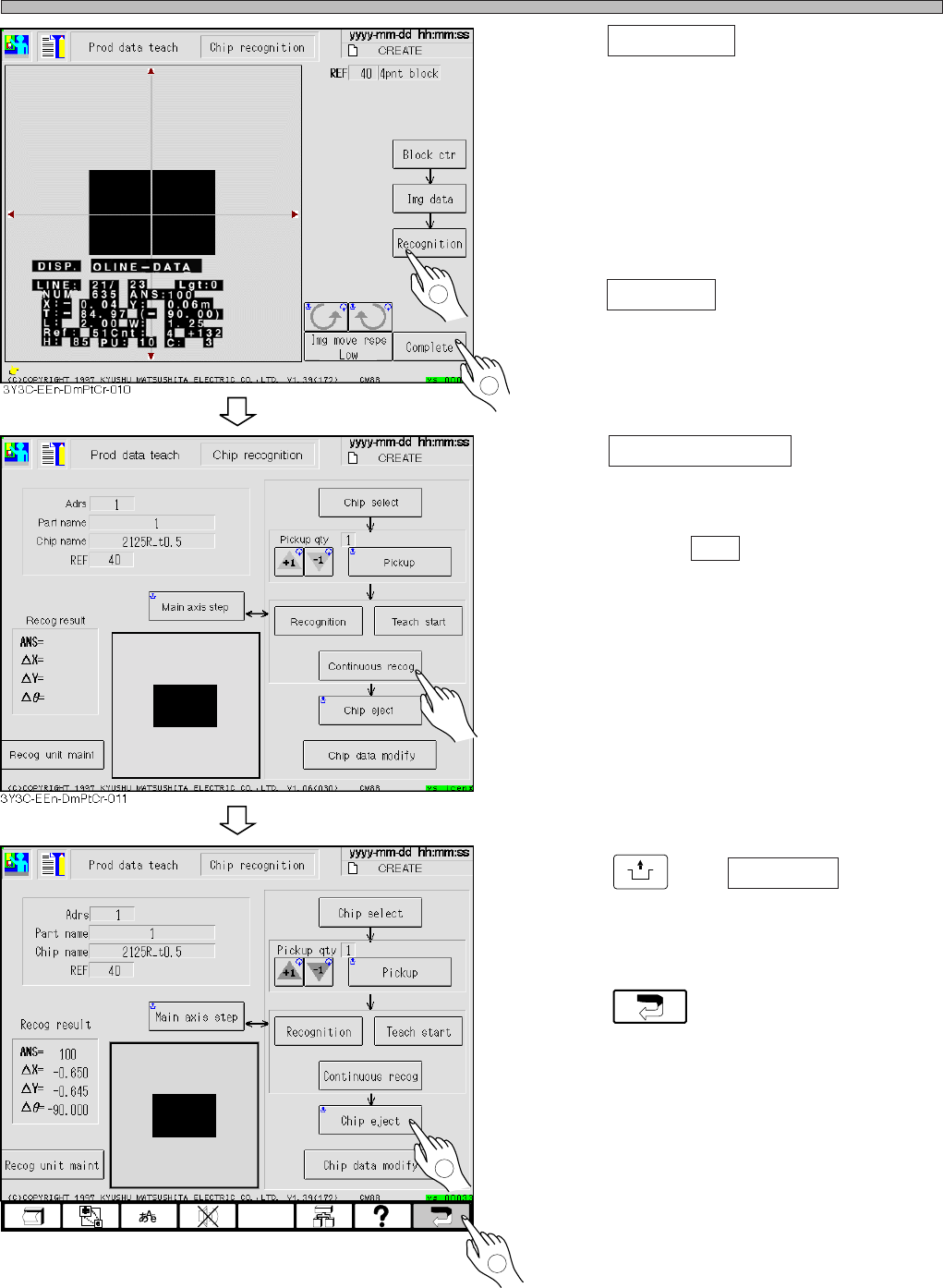
24. Press Recognition .
• Recognition result appears on the recognition
screen.
∗ When the recognition result (ANS=) is under
the recognition rate (judgment value of
machine parameter), retry the procedures 8 to
25 changing the recognition point and so on.
25. Press Complete .
• Teaching is completed.
26. Press Continuous recog (for check) .
• Recognition is repeated 100 times in succes-
sion, and the result is displayed. After checking
the result, press ESC to close the recognition
result.
(This is just for checking, so it is unnecessary
to manage.)
∗ When the recognition result (ANS=) is under
the recognition rate (judgment value of
machine parameter), retry the procedures 8 to
25 changing the recognition point and so on.
27. Press
UNLOCK
and Chip eject .
• Chip used for recognition is carried out.
28. Press .
• 4-point block matching recognition teaching is
finished.
• At this time, the taught data are uploaded to
the PT.
3Y3C-E-EMD05-A01-00
1
2
1
3Y3C-EEn-DmPtCr-012
2
Page 5-25
TEACHING
5
5-5 Teaching the Mount Position
5-5-1 Teaching the Mount Position
When mount position on the same pattern of production board deviates in succession, it can be
corrected by teaching mount position.
Teaching mount position has three kinds of teaching modes, use them for each mount position
deviation.
1 Mount
When only the mount position of specified sequence is deviated, use this. The mount data coordi-
nate of taught sequence is changed.
2 Mount / block
When the mount position at the same position in each block is deviated, use this. All mount data
coordinates of the same block No. as taught chips, and applicable block data are changed.
3 Pattern
When mount position is deviated as a whole, in spite of proper data for board recognition, use this.
Change the origin offset and board recognition coordinate, and use the changed coordinate
distance of taught chips to all chips.
NOTICE
Before using these teaching, check that CAD data corresponds to the data used.
These teaching is the same operation as changing CAD data, so manage data
properly after teaching.
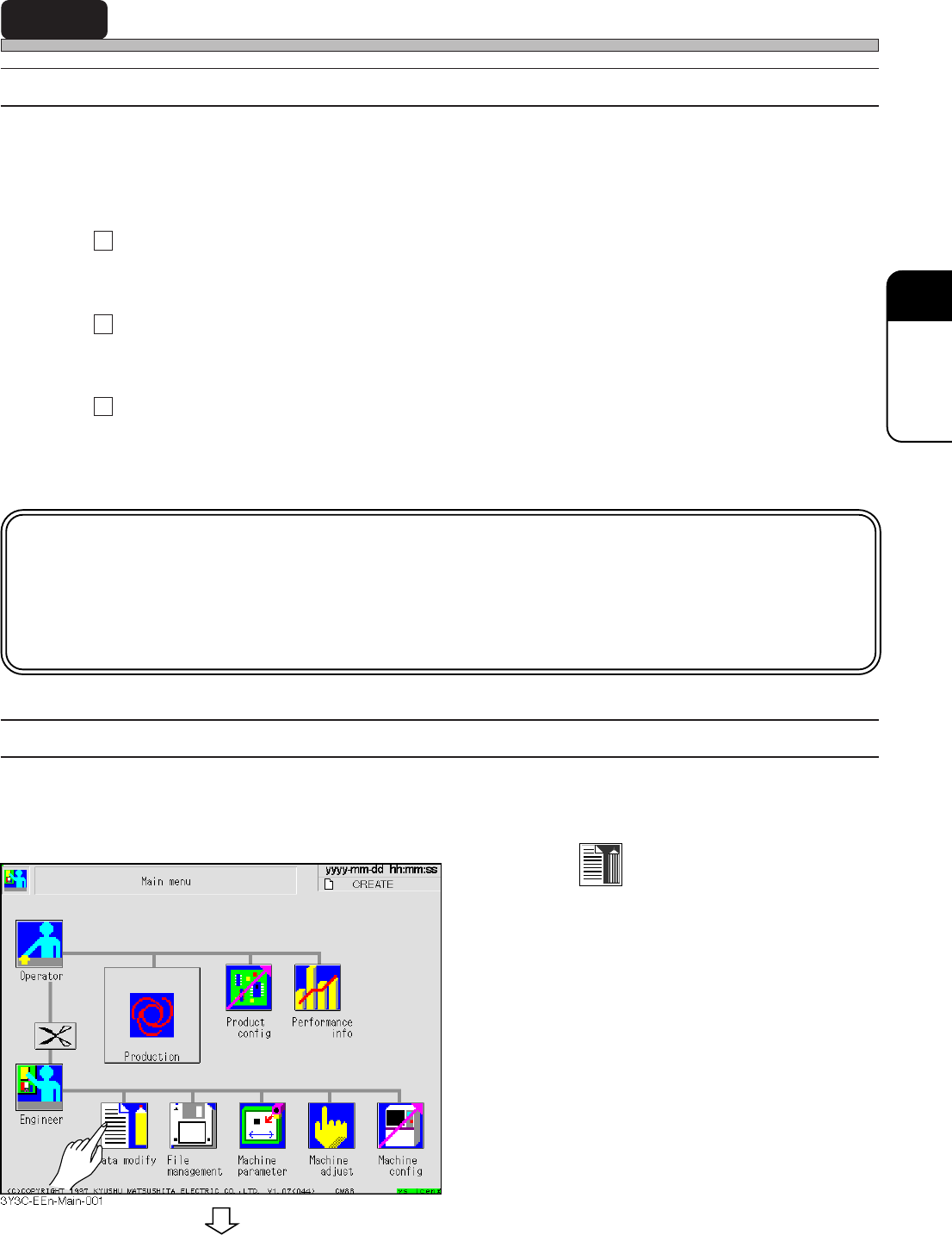
5-5-2 Creating Procedure
This section describes representative procedure of mount teaching.
1. Press
Data modify
.
• Data modification menu screen appears.
3Y3C-E-EMD05-A01-00
To the next page