OPERATING MANAUAL(FOR ENGINEERS) - 第149页
Page 7-5 MACHINE ADJUSTMENT 7 3Y3C-E-EMD07-A01-01 In selecting head In selecting nozzle Move unit T remor Move unit Standard 3Y3C-052E Head 90.00[˚ ] 7-4 Inching Only selected axis can be moved alone, and the movement ca…
Page 7-4
3Y3C-E-EMD07-A01-00
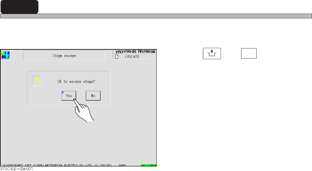
7-3 Stage Escape
This is the function to move A and B stages to each end (origin position) of a feeder drive axis.
Use this for the maintenance at the rear side of machine.
1. Press
UNLOCK
and Yes .
• Stage is retracted.
Page 7-5
MACHINE
ADJUSTMENT
7
3Y3C-E-EMD07-A01-01
In selecting head
In selecting nozzle
Move unit
Tremor
Move unit
Standard
3Y3C-052E
Head
90.00[˚ ]
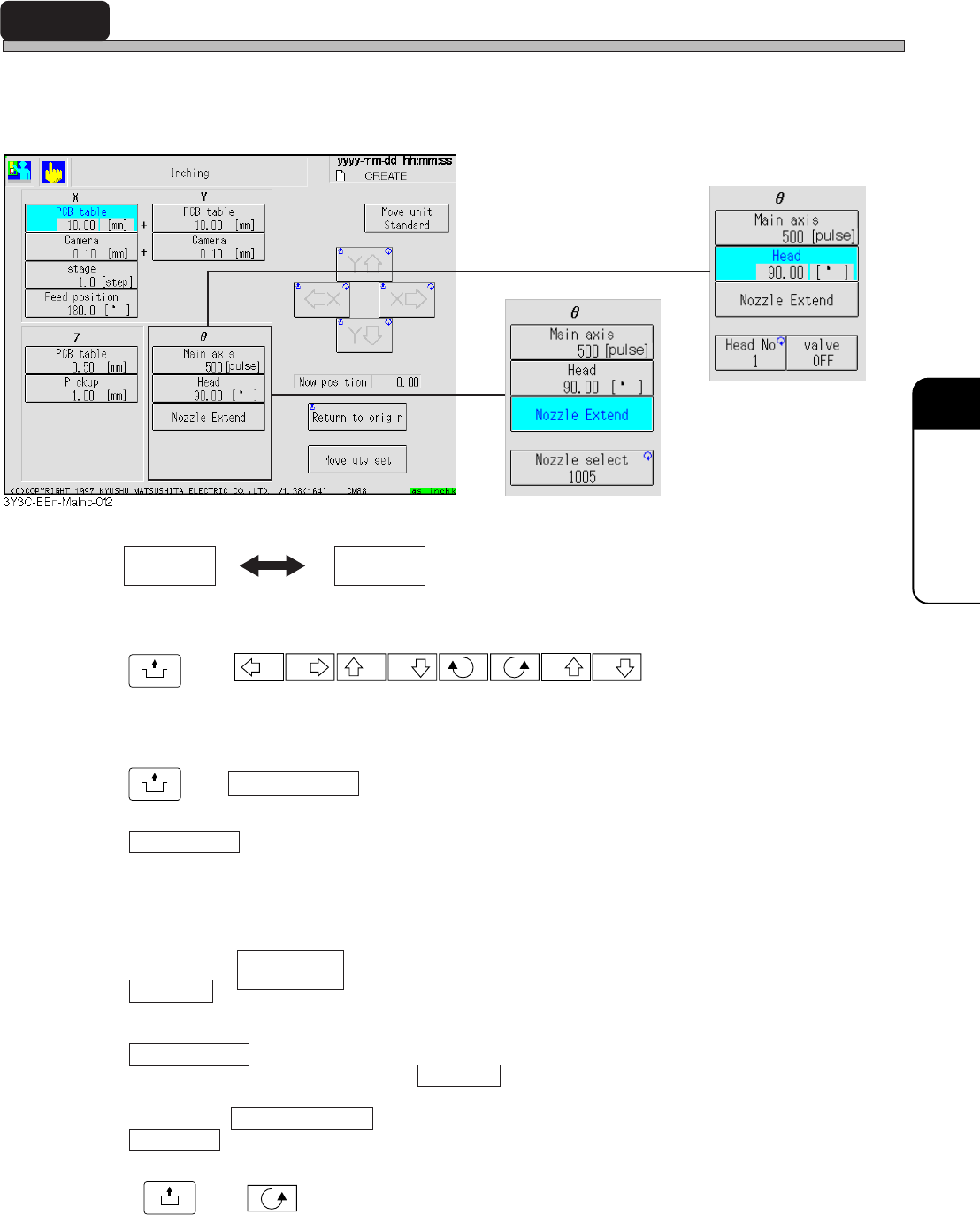
7-4 Inching
Only selected axis can be moved alone, and the movement can be checked and adjusted.
Each axis can be moved to the set direction by set distance. Every selection of axis displays the
arrow button corresponding to the moving direction of selected axis.
Moving unit of axis has Standard and Tremor. Every press of this button exchanges the displays
in turn. Moving rate of each axis is displayed at the lower part of button for each axis.
UNLOCK
and
X X Y Y Z Z
Selected axis is moved to the arrow mark direction by displayed moving rate.
Current position
Current position of selected axis is displayed.
UNLOCK
and Return to origin
Selected axis is returned to origin.
Move qty set
Pressing this button displays numerical keys.
When moving the selected axis by moving rate other than “Standard” or “Tremor,” moving rate
can be set optionally by using this key.
In selecting
Head No.
Pressing this button repeatedly enables to set the head No. to work. At first, the head No. of chip
pickup position station is set.
Vacuum valve
Vacuum valve of head selected by Head No. is turned on and off.
In selecting Nozzle extension
Nozzle sel
Pressing this button repeatedly enables to specify the kind of nozzle. After selecting, pressing
UNLOCK
and makes the main axis (main axis) move by step, and “Nozzle extension” is
carried out for all the nozzle selected by all heads.
Page 7-6
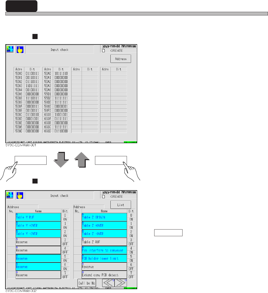
7-5 Input Check
All input address used by machine is sampled every second, and that state is displayed in bit.
Display of List
Display of each address
• The input address used by the machine is
displayed with a name for each bit.
Highlighted button indicates the corresponding
bit is turned on (1).
Pressing “Name” enables to check that bit
again and displays it again.
Call by No.
Address with the specified No. is displayed on
the left of screen.
Address List
3Y3C-E-EMD07-A01-00