OPERATING MANAUAL(FOR ENGINEERS) - 第153页
Page 7-9 MACHINE ADJUSTMENT 7 7-8 Recognition Unit Maintenance All recognition process can be checked. ( Appendix A) Ref no Current setting value of reference No. is checked and changed. It can be changed by . Threshold …
Page 7-8
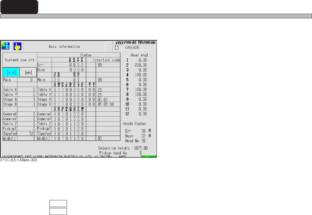
7-7 Axis Information
The current position or status of all axes controlled by the machine can be checked.
<Description of Items>
Current pos cot
Current position of each axis is displayed in mm or pulse of status address.
pls : Current position is displayed in pulse
mm : Current position is displayed in mm.
Status
Status address of each axis, error, and busy are displayed in bit or hexadecimally.
Head angle
Current angle of each head is displayed.
Head status
Status address of head is displayed in hexadecimal. (Only the head No. is described in decimal.)
Detection height
Current non-shield height of height detecting sensor is indicated.
Pickup head No.
Head No. on current pickup position station is indicated.
<Description of Abbreviations>
SB : Stage B OT : Returning to origin time over
SA : Stage A CE : Counter error
TY : Table Y IO : Outputting INT
TX : Table X BU : Busy
DR : Driver error CF : Frequency stable
MO: Minus overrun R6 : Selecting R6
PO : Plus overrun C0 : Counter =0
IE : Interlock error OR: Current origin position
DE : Data error PT : Positioning time over
FE : Feedback error SI : X-Y joint soft interlock error
BE : Buffer empty
3Y3C-E-EMD07-A01-01
Page 7-9
MACHINE
ADJUSTMENT
7
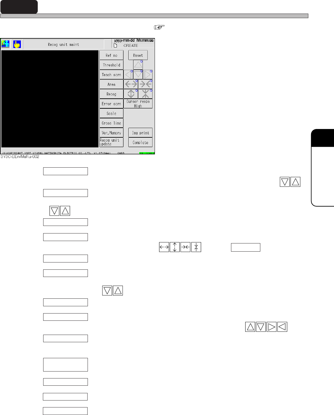
7-8 Recognition Unit Maintenance
All recognition process can be checked. ( Appendix A)
Ref no
Current setting value of reference No. is checked and changed. It can be changed by .
Threshold
Current setting value of binary threshold can be checked and changed. It can be changed by
.
Teach scrn
When reference No. set now is block, teaching screen is displayed.
Area
Area is set as a test. Area is changed by . Pressing Complete sets the area.
Recog
Recognition is carried out under the condition set now.
Error scrn
Recognition error screen occurred by now can be checked to maximum of 110 screens. Screen
can be changed by .
Scale
Scale is displayed on the screen.
Cross line
Cross hair is displayed on the recognition screen. Position is changed by .
Ver, Memory
Current version of recognition system and recognition ROM is displayed on the recognition
system.
Recognition system can be updated.
Reset
In selecting “Area,” “Error screen,” and “Cross line,” each information can be reset.
In selecting “Ref No.,” “Threshold,” “Area,” and “Cross line,” each changing rate can be adjusted.
Img print
Recognition image displayed on the touch panel can be printed.
Recog unit
update
3Y3C-E-EMD07-A01-00
Cursor resps

Page 7-10
Recognition Unit Maintenance
7-8-1 Recognition Unit Update
This section describes updating the recognition system.
Copy the recognition system from the floppy disk with recognition system to be upgraded to RAM,
and after comparing (inspecting by reading) the system of floppy disk with that of RAM, the system
is written to the memory if no trouble is found.
<Description of Items>
ROM version : Current recognition ROM version
System version : Version of recognition system to upload
All blocks : Current recognition system volume
Transferring blocks : Transferred recognition system volume
∗ Refer to “Chapter 4 UPDATING” in the Maintenance Manual for the details.
3Y3C-E-EMD07-A01-01