OPERATING MANAUAL(FOR ENGINEERS) - 第164页
Page 8-10 3Y3C-E-EMD08-A01-01 Setting the operator customization 3) Immediate stop screen when the data modification and the machine configuration are selected • When it is the immediate stop screen in the operator mode,…
Page 8-9
MACHINE SETTING
8
Setting the Operator Customization
8-6-2 Immediate Stop Screen in the Customization Setting (In
Operator Mode)
This section describes the data modification, machine configuration, and the immediate stop
screen when they are set to “Use,” in setting the operator customization.
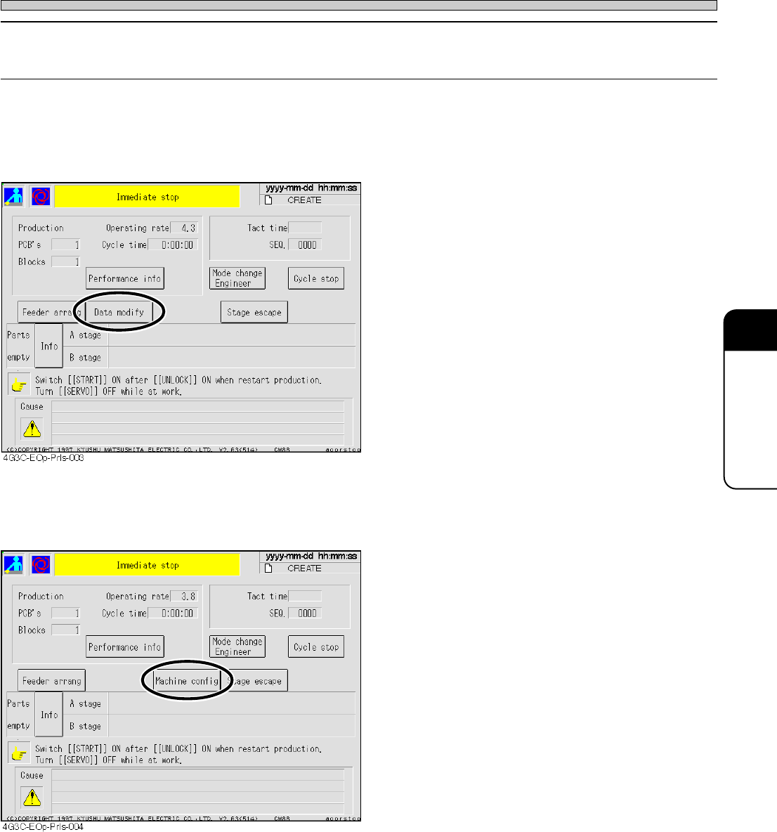
1) Immediate stop screen when the data modification is selected
• When it is the immediate stop screen in the
operator mode, the item of data modification
appears.
∗ The switch displayed on the immediate stop
screen is effective only in data modification and
machine configuration.
2) Immediate stop screen when the machine configuration is selected
• When it is the immediate stop screen in the
operator mode, the item of machine configura-
tion appears.
∗ The switch displayed on the immediate stop
screen is effective only in data modification and
machine configuration.
3Y3C-E-EMD08-A01-01
Page 8-10
3Y3C-E-EMD08-A01-01
Setting the operator customization
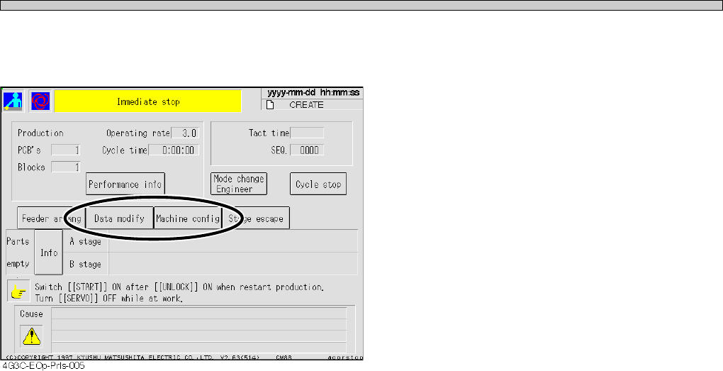
3) Immediate stop screen when the data modification and the machine configuration
are selected
• When it is the immediate stop screen in the
operator mode, the item of data modification
and machine configuration appears.
∗ The switch displayed on the immediate stop
screen is effective only in data modification and
machine configuration.

Page 1
A
A st ...................................................................8-3
Accessories and spare parts..........................1-18
Adjusting pin positioning unit (option) ..............3-8
Adjusting the transport rail width ......................3-5
Adjustment switch ............................................8-2
All blocks ........................................................7-10
All pin clear ....................................................4-11
All reset ............................................................8-3
Angle definition ................................................4-9
Area..................................................................7-9
Automatic correction of the pickup position .....1-5
Available range of board warp .......................1-15
Axis information .......................................2-8, 7-8
B
B st...................................................................8-3
Bad board mark inspection ............................4-16
Bad head..........................................................8-4
Bad mark detecting time ................................1-10
Bad nozzle .......................................................8-5
Bad PCB mark pos ..........................................4-3
Before teaching the chip recognition..............5-16
Block attribute data ................................4-2, 4-14
Block matching recognition (chip recognition) 5-2
Board changing time ......................................1-10
Board data .......................................................4-3
Board edge reference ....................................1-11
Board flow direction..............................1-10, 1-12
Board holder.....................................................3-1
Board recognition mark..................................1-15
Board size ......................................................1-15
Board X-Y table................................................3-1
C
Carry in.............................................................7-3
Carry out ..........................................................7-3
Center conveyor...............................................7-7
Changing production board..............................3-1
Changing production data................................3-2
Changing the password ...................................2-5
Check period indicator .....................................2-3
Checking the mounting by conditional mounting ...
3-13
Chip data........................................................4-10
Chip feeding .....................................................8-2
Chip mounting..................................................1-7
Chip name........................................................8-3
Chip pickup ......................................................1-7
Chip recognition .......................................1-7, 8-2
Complete part information................................4-8
Control system ...............................................1-10
Conveyor width adjustment..............................7-2
Coordinate origin..............................................4-3
Cross line .........................................................7-9
Current pos cnt.................................................2-8
Current pos cot.................................................7-8
Cursor resps.....................................................7-9
D
Data check .............................................4-2, 4-17
Data modification menu ...................................4-2
Deleting data ..................................................6-15
Detect chip thick...............................................8-2
Detection height .......................................2-8, 7-8
Diagram of indexing unit ..................................1-6
Display of each address...........................7-6, 7-7
Display of solenoid...........................................7-7
E
Environmental condition.................................1-10
Error scrn .........................................................7-9
Evolution data ..................................................4-6
Exchange mode ...............................................1-8
Extend conv W adj ...........................................8-2
Extension chip data........................................4-11
External memory............................................1-10
F
Features...........................................................1-2
Feeder layout / Stock data .......................4-2, 4-7
Fiducial data.............................................4-2, 4-4
File operation ...................................................6-1
File operation of floppy disk .............................6-5
File operation of PT100....................................6-2
Form print...............................................4-2, 4-18
Front ( rear) transferring conveyor....................3-1
Function switch ..............................................4-16
Functions during stopping production ..............2-6
Functions of the engineer mode ......................2-2
Functions of the main menu.............................2-3
Functions of the menu tree ..............................2-4
H
Head angle...............................................2-8, 7-8
Head No...........................................................7-5
Head status..............................................2-8, 7-8
Height detection ...............................................1-7
Height detection head angular rotation ............1-7
High productivity...............................................1-2
High-quality mounting ......................................1-3
I
Img print ...........................................................7-9
Inching .............................................................7-5
Initializing a floppy disk ..................................6-16
Input check.......................................................7-6
J
Joint mode........................................................1-9
3Y3C-E-EMA0Y-A01-02