OPERATING MANAUAL(FOR ENGINEERS) - 第64页
Page 2-8 Functions during Stopping Production [Recognition] • Considering ST A No. = 1 a pickup position, the recognition information of head from ST A No. 3 to 6 is displayed to the rotating direction. ST A. = 1 .......…
Page 2-7
BASIC OPERATION
2
Functions during Stopping Production
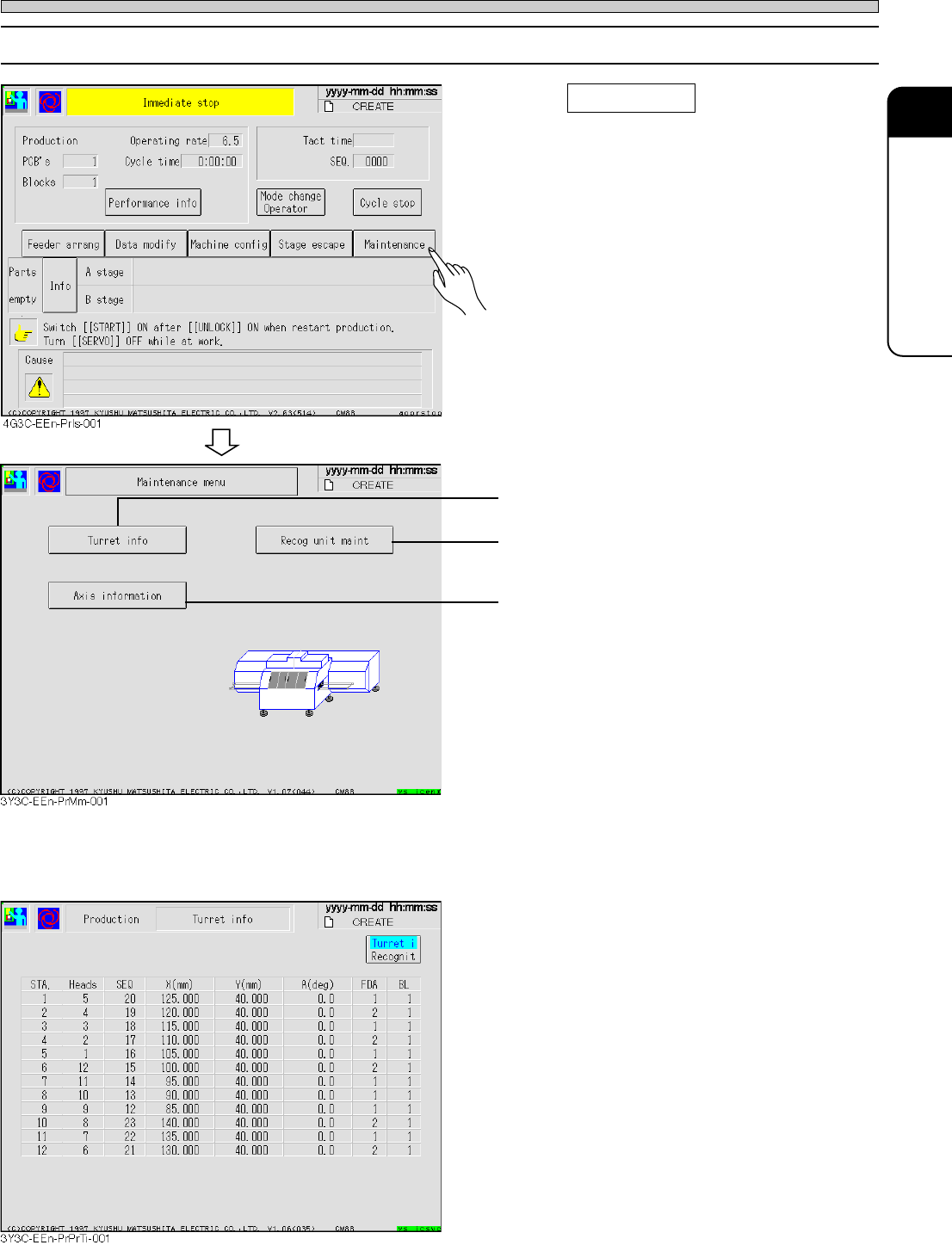
2-2-1 Maintenance
1. Press Maintenance .
• Maintenance during the automatic operation is
carried out.
• Information held in each head can be checked.
• All recognition processes can be checked.
See “7-8 Recognition Unit Maintenance.”
• Current position and status of all axes con-
trolled by machine can be checked.
See “7-7 Axis Information”
a) Turret information
The information in each head can be checked.
[Turret information]
• Considering STA No. = 1 as the pickup
position, data information of each head is
displayed to the rotating direction.
Head = Head No.
SEQ = SEQ No.
X, Y, and A = Coordinate and angle of mount
data
FDA = Feeder address
BL = Block No.
∗ For the head without data, items after SEQ is
not displayed.
3Y3C-E-EMD02-A01-01
Page 2-8
Functions during Stopping Production
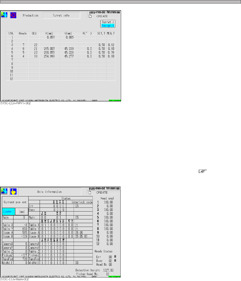
[Recognition]
• Considering STA No. = 1 a pickup position, the
recognition information of head from STA No. 3
to 6 is displayed to the rotating direction.
STA. = 1 ............. Corrected positional value is
displayed to X and Y.
X,Y and A ............Coordinates and angle after
correcting recognition.
(from STA No 4 to 6)
SEA. T ................ Setting value of chip thick
ness
(First measured value after
parts supply)
MEA. T ............... Measured value of chip
thickness
∗ For the head without data, items after SEQ is
not displayed.
For the head of pickup fault, items after X is not
displayed.
When chip feeding is turned off by function
switch, items after SET. T is not displayed.
b) Axis information
Present position and status of all axes controlled by machine can be checked ( “7-7 Axis
information”).
[Items]
• Current pos cnt
Current position of each axis is displayed in
mm and pulse.
• Status
Status address of each axis, error and busy
are displayed in bit or hexadecimally.
• Head angle
Current angle of each head is displayed.
• Head status
Status address of head is displayed in hexa-
decimal. (Only the head No. is described in
decimal.)
• Detection height
Present non-shield height of height dispensing
sensor is displayed in mm or pulse.
• Pickup head No.
Head No. on current pickup section is indi-
cated.
3Y3C-E-EMD02-A01-02
Page 3-1
3Y3C-E-EMD03-A01-01
Chapter 3
CHANGING PRODUCTION
CHANGING PRODUCTION
BOARD
BOARD
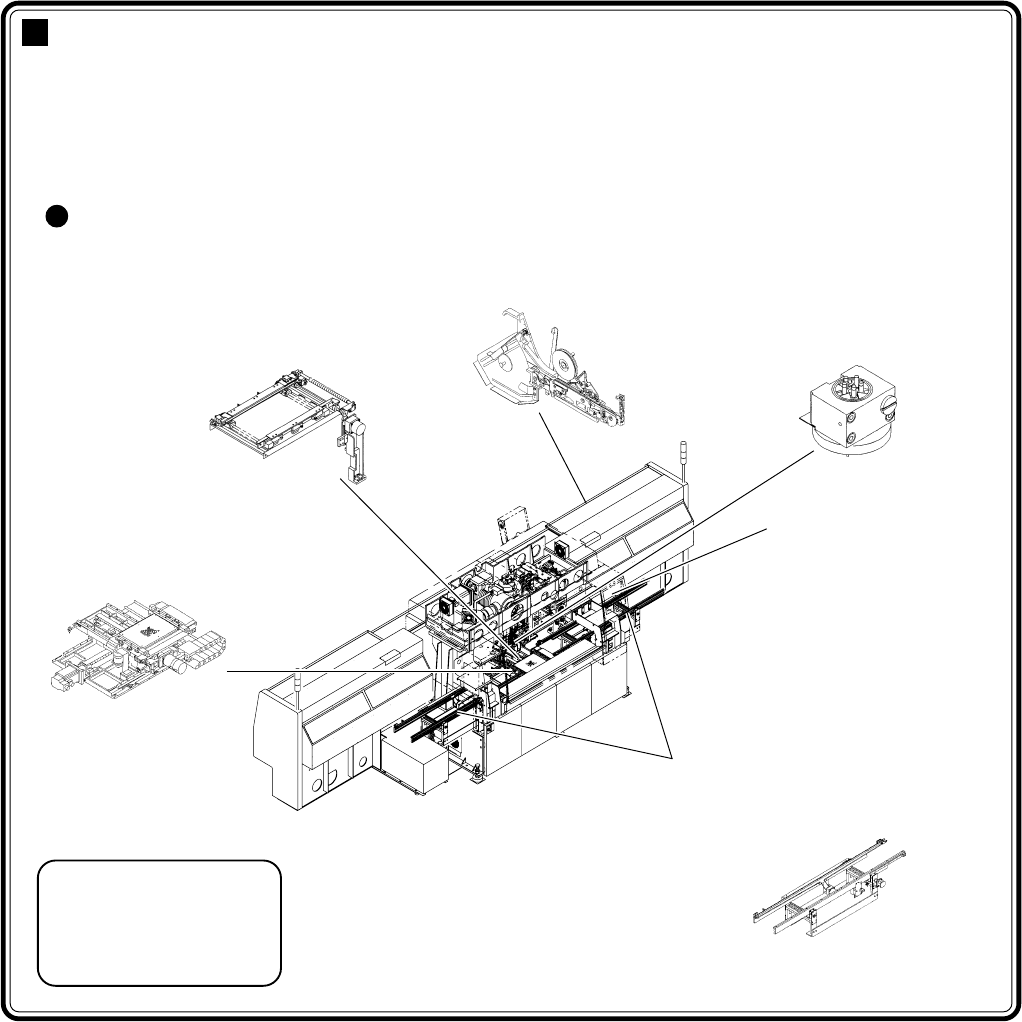
Changing production board
For mounting the parts on different board from the former, it is necessary to adjust
units or supply production materials according to the board.
This section describes the operation for changing the production board, considering
that the data of it is on the PT100.
Machine adjustment points due to the change of production board
Board holder
Transferring rail width
adjustment (automatic)
Setting tape feeder
Transfer head
Nozzle change
(change if necessary)
Board X-Y table
Operating part
Holder pin position adjustment
(manual)
Production data change
(manual)
Front (rear) transferring conveyor
Transferring rail width adjustment
(automatic)
Pin positioning unit
(option)
Pin position adjustment
(manual)
4G3C-AE01
07JHC2AA
15ULC0AA
TAPE-002
1231C1AA
11DGC2AA