OPERATING MANAUAL(FOR ENGINEERS) - 第8页
Page 8 Chapter 6 6 FILE OPERA TION 6-1 File Operation of PT100 ............................................................................. 6-2 6-1-1 Loading Data ........................................................…
Page 7
3-7 Checking the Mounting by Conditional Mounting ..................................... 3-13
Chapter
44
DATA MODIFICATION
4-1 Data Modification Menu.............................................................................. 4-2
4-2 Board Data ................................................................................................. 4-3
4-3 Fiducial Data .............................................................................................. 4-4
4-3-1 Selecting REF .....................................................................................................4-5
4-3-2 Evolution Data.....................................................................................................4-6
4-4 Feeder Layout / Stock Data........................................................................ 4-7
4-4-1 Occupancy ..........................................................................................................4-8
4-4-2 Complete Part Information ..................................................................................4-8
4-4-3 Angle Definition...................................................................................................4-9
4-5 Chip Data ................................................................................................. 4-10
4-5-1 Extension Chip Data .........................................................................................4-11
4-5-2 Selecting the Nozzle .........................................................................................4-12
4-5-3 Selecting REF ...................................................................................................4-12
4-5-4 Selecting the Camera........................................................................................4-13
4-6 Block Attribute Data.................................................................................. 4-14
4-7 Mount Data............................................................................................... 4-15
4-8 Function Switch ........................................................................................ 4-16
4-9 Data Check............................................................................................... 4-17
4-10 Form Print................................................................................................. 4-18
Chapter
55
TEACHING
5-1 Before Teaching.......................................................................................... 5-2
5-1-1 Recognition Method ............................................................................................5-2
5-2 Teaching the Board Recognition ................................................................ 5-3
5-2-1 Board Recognition ..............................................................................................5-3
5-2-2 Flow Chart of Teaching the Board Recognition...................................................5-3
5-2-3 Creating Procedure.............................................................................................5-4
5-3 Teaching the Bad Mark Recognition........................................................... 5-8
5-3-1 Bad Mark Recognition.........................................................................................5-8
5-3-2 Flow Chart of Teaching the Bad Mark Recognition .............................................5-8
5-3-3 Creating Procedure.............................................................................................5-9
5-4 Teaching the Chip Recognition................................................................. 5-14
5-4-1 Chip Recognition...............................................................................................5-14
5-4-2 Flow Chart of Teaching the Chip Recognition ...................................................5-14
5-4-3 Before Teaching the Chip Recognition..............................................................5-16
5-4-4 Procedure of Block Matching Recognition ........................................................5-19
5-5 Teaching the Mount Position .................................................................... 5-25
5-5-1 Teaching the Mount Position .............................................................................5-25
5-5-2 Creating Procedure...........................................................................................5-25
4G3C-E-EMA00-A02-00
Page 8
Chapter
66
FILE OPERATION
6-1 File Operation of PT100 ............................................................................. 6-2
6-1-1 Loading Data.......................................................................................................6-3
6-2 File Operation of Floppy Disk ..................................................................... 6-5
6-2-1 Loading Data.......................................................................................................6-6
6-2-2 Saving Data ........................................................................................................6-8
6-2-3 Loading and Saving the Machine Parameter....................................................6-11
6-2-4 Loading the Coordinate Data ............................................................................6-13
6-2-5 Loading the Recognition Data...........................................................................6-14
6-2-6 Deleting Data ....................................................................................................6-15
6-2-7 Initializing a Floppy Disk....................................................................................6-16
Chapter
77
MACHINE ADJUSTMENT
7-1 Conveyor Width Adjustment ....................................................................... 7-2
7-2 PCB Transfer.............................................................................................. 7-3
7-3 Stage Escape ............................................................................................. 7-4
7-4 Inching........................................................................................................ 7-5
7-5 Input Check ................................................................................................ 7-6
7-6 Output Check ............................................................................................. 7-7
7-7 Axis Information.......................................................................................... 7-8
7-8 Recognition Unit Maintenance ................................................................... 7-9
7-8-1 Recognition Unit Update ...................................................................................7-10
Chapter
88
MACHINE SETTING
8-1 Adjustment Switch...................................................................................... 8-2
8-2 Pickup Position Learning............................................................................ 8-3
8-3 Bad Head ................................................................................................... 8-4
8-3-1 Bad Nozzle..........................................................................................................8-5
8-4 Time Setting ............................................................................................... 8-6
8-5 Speed Setting............................................................................................. 8-6
8-6 Setting the Operator Customization ........................................................... 8-7
8-6-1 Setting the Function of Operator Customization .................................................8-7
8-6-2 Immediate Stop Screen in Setting the Customization (In Operator Mode) .........8-9
INDEX
Appendix
AA
RECOGNITION DEVICE
4G3C-E-EMA00-A02-00
Page 9
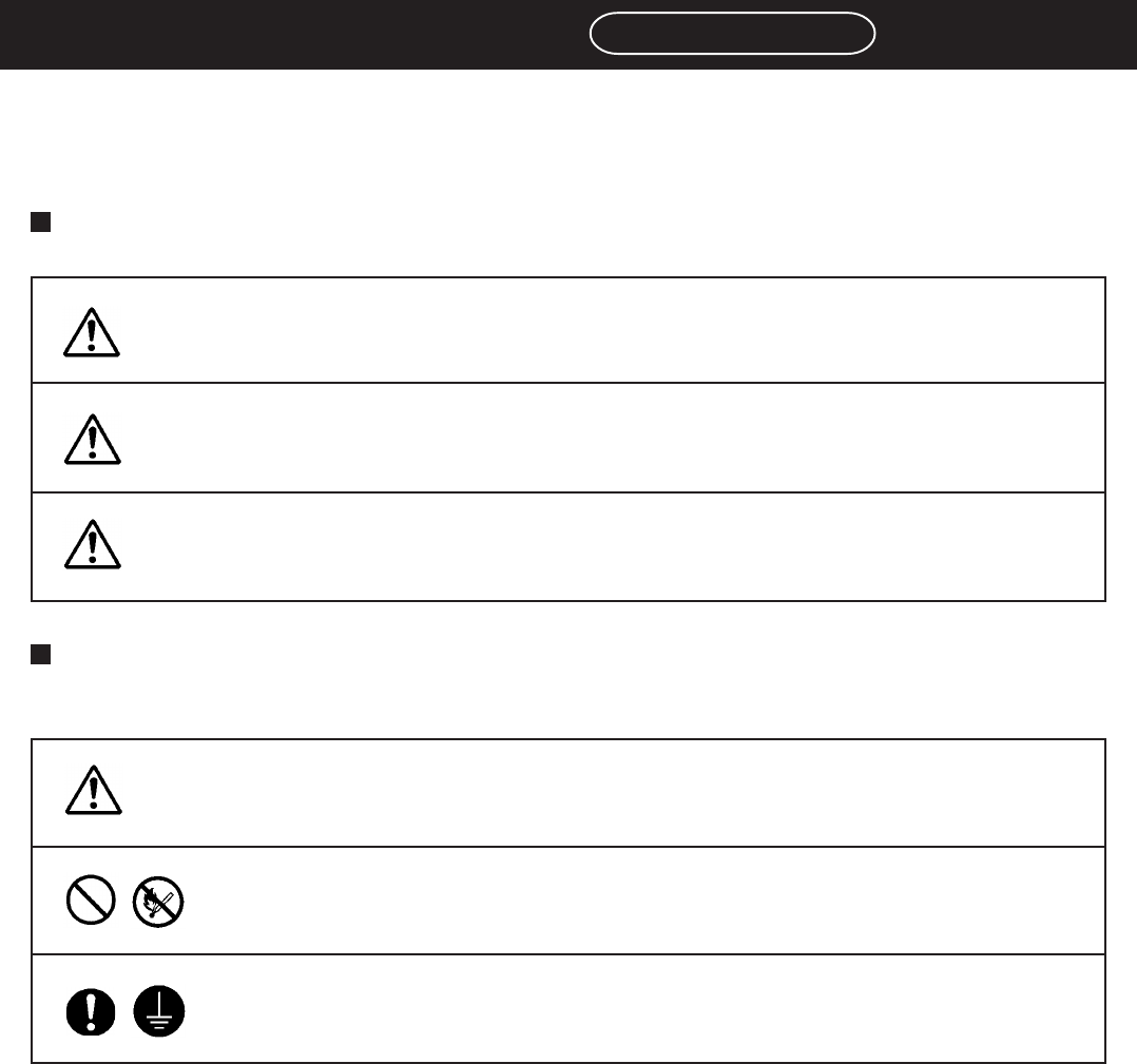
SAFETY PRECAUTIONS
Be sure to observe
The precautions that must be observed in order to prevent injury to the user or another
person, or damage to property, are as follows.
The degree of danger or injury resulting from incorrect use due to the failure to read an
indication is classified and described as follows.
The matters should be observed are classified and described according to the symbols
shown below.
(The followings are only some examples of the symbolic indications.)
This indication refers to a situation which is considered that
there is imminent danger of death or serious injury.
This indication refers to a situation which is considered that
there is a possibility of death or serious injury.
This indication refers to a situation which is considered that
there is a possibility of only injury or physical damage.
These symbols indicate matters to which attention must be paid.
This symbol indicates an action that must not be carried out.
DANGER
WARNING
CAUTION
This symbol indicates an action that must be carried out.
3Y3C-E-EMD00-A03-00