00198171-02_Technical_Training_FSE_TX-Series_EN.pdf - 第103页
7 Power Supply 7.8 Safety control Technical Training FSE SIPLACE TX-Series 01/2018 103 ● Safety control of output voltages 300/160/42 and 24 V ● Pre-charge external capacitors (300 and 160V lines) within 1s, to avoid una…
7 Power Supply
7.7 SMPS diagnostic
102 Technical Training FSE SIPLACE TX-Series 01/2018
7.7 SMPS diagnostic
The diagnostics function in the station software provides easy monitoring of the machine voltage
status.
The following analysis and monitoring options are possible:
●
Monitoring of power pack PS1 and capacitor battery CAP
●
Monitoring of safety states on the CSB
●
Monitoring of intermediate circuit voltages placement heads 160VDC on the FD
●
Monitoring of voltages 42VDC / 28VDC / 24VDC on the FD
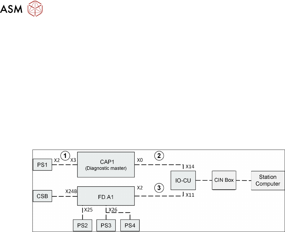
For monitoring the power pack voltages and the fuses on the CAP & FD above, there are also two
additional diagnostics circuits within the SMPS, these two diagnostics circuits are combined on the
IOCU and transferred to the station computer from there.
The connections 1, 2 and 3 are used only to pass on diagnostics data and are therefore essential if
the diagnostics function is to work properly.
●
In order for the diagnostics GUI to function properly, the SMPS cables must be connected cor-
rectly. In case of troubleshooting ensure that all cables are connected correctly. If machine
controller does not receive any diagnostics data for the capacitor battery (e.g. malfunction or
missing cable connection), no diagnostics information will be shown for the FD also!
The Diagnostics Master is a fixed part integrated in the CAP1; it evaluates the information from the
entire PS1-CAP1 assembly as needed for diagnostics.
In addition, the data from the CAP1 capacitor battery (charging status, temperature, backup stor-
age capacity, working time) are queried by the Diagnostics Master.
FD.A1 collects all diagnostics data for the low voltage monitoring (from PS2/PS3/PS4 / fuses on
FD) and safety logic (from CSB). The diagnostics data is then sent from the FD to the IOCU.
The information about the 160VDC is also queried for the intermediate circuit voltage of the place-
ment heads. This takes place via the logic on fuses F19 and F20.
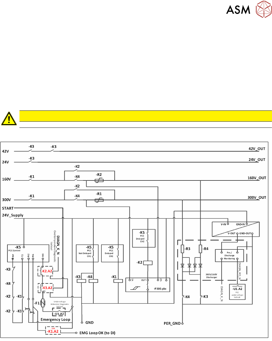
7.8 Safety control
Safety control of output voltages is provided by unit CSB (Contactor based Safety Breaker), which
consists of two functional units:
1. Circuit Safety Contact Breaker Unit
2. Pre/discharge board –A2, for monitoring and suppressing the load current of the main axes.
The unit provides functionality for,
7 Power Supply
7.8 Safety control
Technical Training FSE SIPLACE TX-Series 01/2018 103
●
Safety control of output voltages 300/160/42 and 24 V
●
Pre-charge external capacitors (300 and 160V lines) within 1s, to avoid unauthorized current
loads on connection when switching on output voltages
●
Discharge external capacitors (300 and 160V lines) within 1s to a value below 60V when
switching off output voltages
●
State signaling to Fuse Diagnostic unit located at FD.A1
●
Power enabled signal to MGCU, HCU and conveyor units
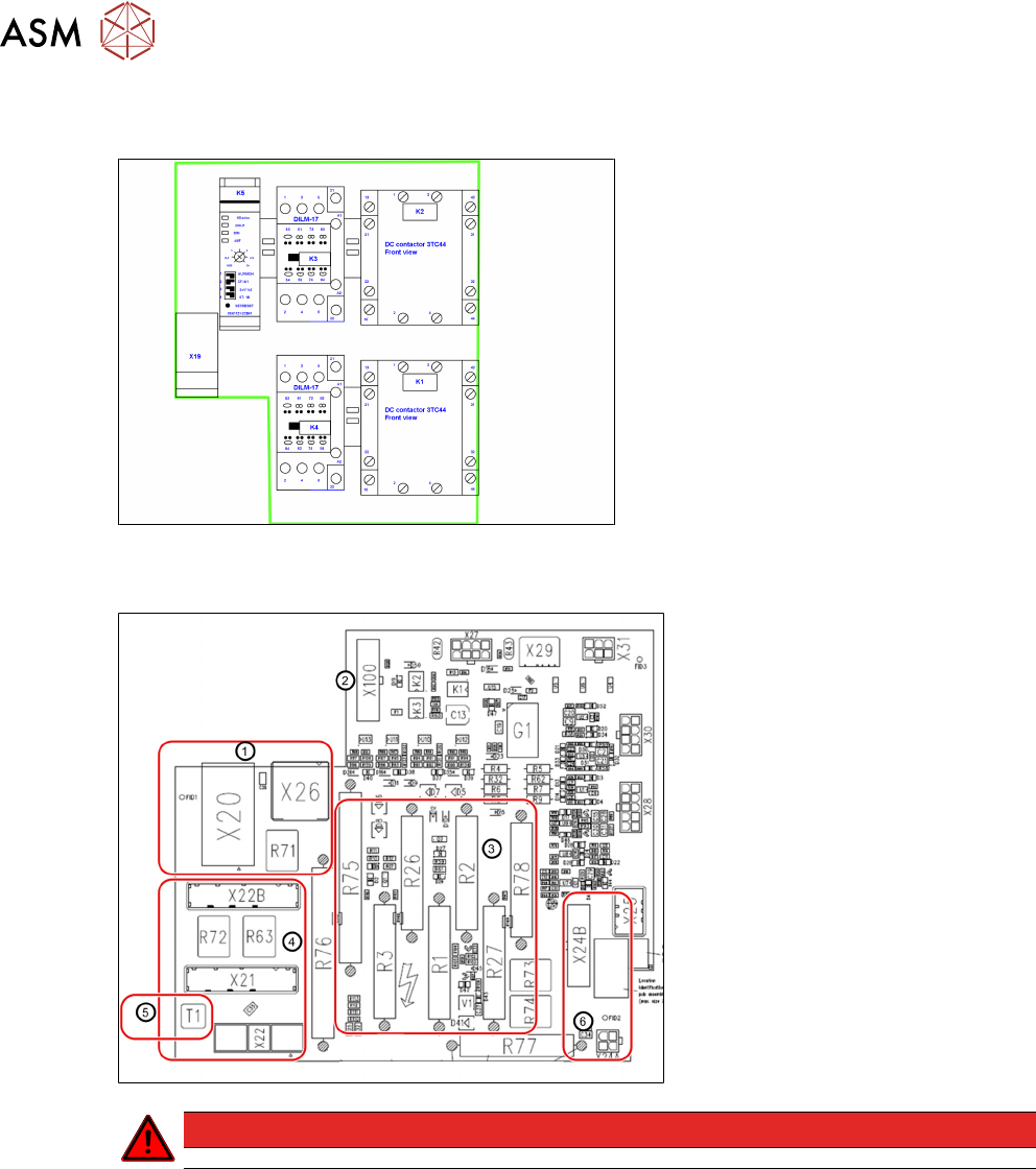
Unit is made of a baseplate that carries contactors and wiring, covered by a PCB carrying all con-
nectors and interfacing
CAUTION
In case of a faulty unit the complete unit needs to be exchanged.
7 Power Supply
7.8 Safety control
104 Technical Training FSE SIPLACE TX-Series 01/2018
CSB Assembly (Safety Relays )
Overview Pre/ discharge board – A2
1. DC Power input
2. Safety Relays connector
3. Discharge resistors
4. 300V link output connectors
5. Functional grounding (PE)
6. Low voltage distribution (FD.A1)
DANGER
Do not open. The unit is completely housed to protect user from dangerous voltages complete
assembly available as a spare part