00198171-02_Technical_Training_FSE_TX-Series_EN.pdf - 第111页
7 Power Supply 7.11 Analysis - Common Error List Technical Training FSE SIPLACE TX-Series 01/2018 111 Error Possible Cause Action Short reaction of CSB after START pressed ● Check precharge current at 300 V DC link volta…
7 Power Supply
7.11 Analysis - Common Error List
110 Technical Training FSE SIPLACE TX-Series 01/2018
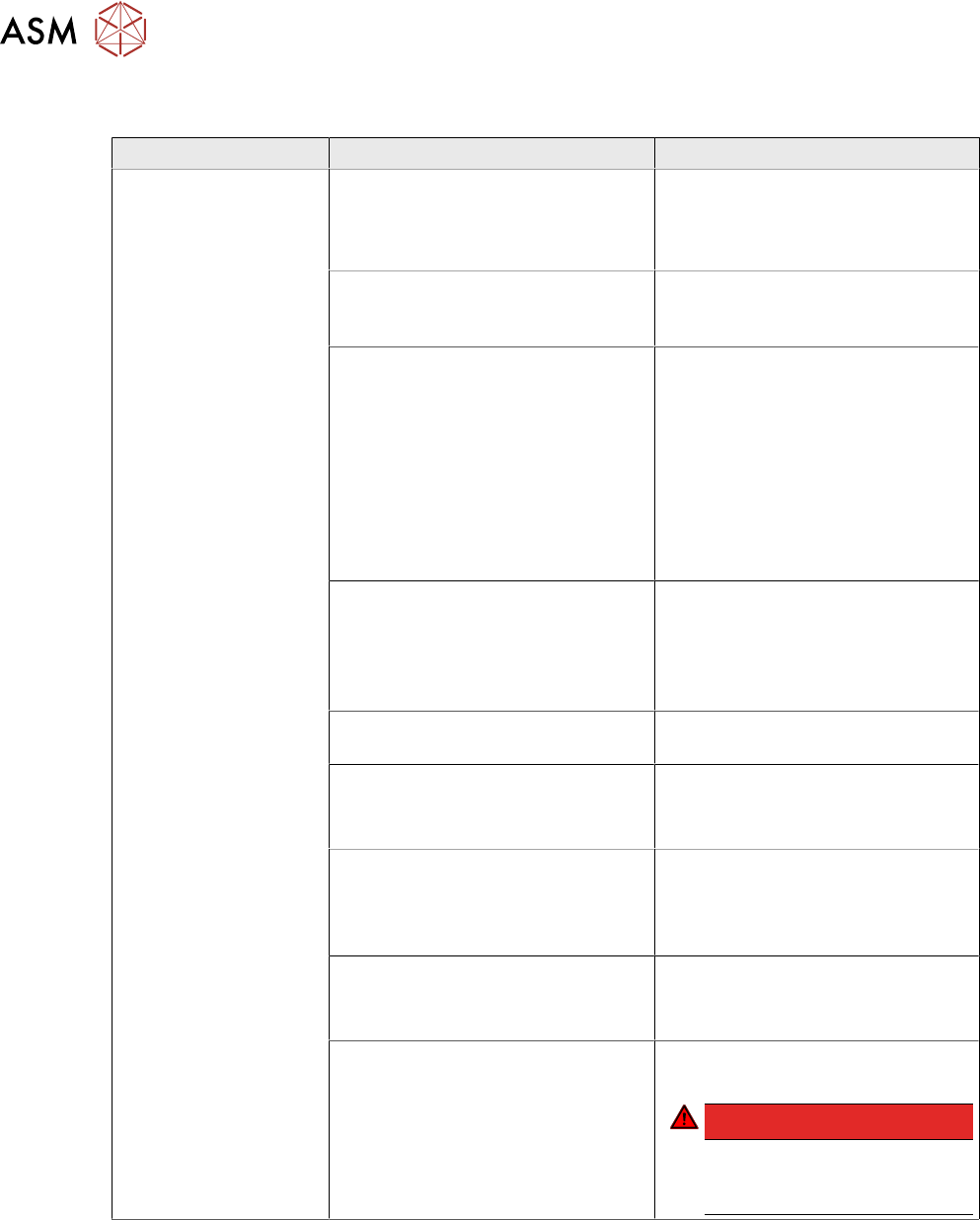
7.11 Analysis - Common Error List
Error Possible Cause Action
No reaction after
START pressed
Duration of pressing and release of
START button
●
Press longer than 200 ms and
shorter than 1500 ms.
START should be accepted on
pushbutton release.
Safety loop closed?
●
Check if both channels of
safety loop show closed con-
dition
SW_CTRL_ON output of IO miss-
ing?
●
Check: (X29.A6) should be
HIGH if START is pressed
●
Check IO wiring.
●
Check IO output.
●
Check START button wiring.
If output is missing:
●
Replace IO unit
●
Fix START button wiring.
Connection to PCB FD.A1 estab-
lished?
●
Check connectors X24A and
X24B at FD.A1 and at PCB
CSB
●
Place connectors firm in posi-
tion.
Ground connection of PCB CSB
missing?
●
Connect terminal lug to
Ground terminal of CSB.
Supply voltage of CSB missing?
●
Check fuses F12 and F13.
●
Replace fuses F12 and F13, if
needed.
Signal PCC-POWER-OK (X24B.5
at PCB,LED at K5)
If voltage reading > 22V or Power
OK LED of K5 is on→ internal de-
fect of CSB:
●
Replace unit
24V Measure input voltage
(X24B.3)
If voltage reading > 22V → internal
defect of CSB:
●
Replace unit
Power connectors of CAP and CSB Connectors should be firm in posi-
tion.
DANGER!
If you check connectors
mind the dangerous
voltage!
.

7 Power Supply
7.11 Analysis - Common Error List
Technical Training FSE SIPLACE TX-Series 01/2018 111
Error Possible Cause Action
Short reaction of CSB
after START pressed
●
Check precharge current at
300 V DC link voltage
If there is no precharge current
(max 10A):
●
Check GND connection of
CSB
Ground connection of PCB CSB
missing?
●
Connect terminal lug to
Ground terminal of CSB.
If there is GND connection estab-
lished:
→ internal defect of CSB;
●
Replace unit
Overload or short circuit at 160 V
DC link output?
●
Remove X24B and try to start.
If Start is working now fix short cir-
cuit conditions at 160V DC link
branch
Overload or short circuit at 300 V
DC link voltage?
●
Remove X21 and X22 and try
to start.
If Start is working now fix short cir-
cuit conditions at 300V DC link
branch
Machine is passing ref-
erence run but stops at
beginning the of pro-
duction run
MGCU Error Message: Under-
voltage error at DC link voltage?
●
Check capacitor value of CAP
unit (service screen of dia-
gnostic functions) has to be >
30 mF
If Capacitor value < 30 mF:
●
Replace capacitor unit
●
Check QT40.999 error mes-
sages at service screen
If QT40 error is shown:
●
Replace QT40 unit.
Service screen QT40 unit
●
Check indicator lights at
QT40-999:
Green light (>220V) should be on
during reference run
red light should be on temporary
during gantry acceleration period
DC 42V-S is missing
(Conveyor supply)
Fuse does not work?
Connector X24A (both PCB’s!)
properly connected?
●
Check supply voltage at
FD.A1, F16
Fuse blown or broken?
●
Replace fuse
●
Place connector firm into
place
If error still occurs
→ internal defect of CS:
●
Replace unit

7 Power Supply
7.12 US option
112 Technical Training FSE SIPLACE TX-Series 01/2018
Error Possible Cause Action
DC24-S is missing Fuse does not work?
Connector X24A (both PCB’s!)
properly connected?
●
Check supply voltage at
FD.A1, F11
Fuse blown or broken?
●
Replace fuse
●
Place connector firm into
place
If error still occurs
→ internal defect of CSB:
●
Replace unit
POWER-Enabled sig-
nal is missing
Fuse does not work?
Connector X24A (both PCB’s!)
properly connected?
Precharge sequence finished?
DC link voltages are ON)?
●
Check supply voltage at
FD.A1, F11
Fuse blown or broken?
●
Replace fuse
●
Place connector firm into
place
If error still occurs
→ internal defect of CSB:
●
Replace unit
Errors at diagnostic interface:
Error Possible Cause Action
No diagnostic display
(Icon is missing)
Wiring of diagnostic master:
●
Connection between PS1 and
CAP established?
●
Connection between CAP and
IOCU2 established (use cros-
sover cable!)?
●
Replace wiring.
If there is still no Diagnostic display
available → Diagnostic master at
CAP unit failure:
●
Replace CAP unit
●
QT40 diagnostic supply
voltage available?
●
Internal fuse at CAP unit
blown?
Voltage reading between Pin 1 and
4 of diagnostic connector should be
DC 5V
●
Check QT40 diagnostic supply
voltage.
●
Check internal fuse at CAP
unit.
●
Check voltage reading
between Pins 1 and 4 of dia-
gnostic connector.
If there is no voltage reading →
CAP unit failure:
●
Replace CAP unit
No fuse diagnostic dis-
play
Wiring to FD.A1:
Connection between FD.A1 and
IOCU2 establisched?
●
Check if FD.A1-X3 is located
firm in its place.
If not:
●
Replace wiring
If there is still no Fuse diagnostics
available:
→ FD.A1 internal error.
●
Replace FD.A1
7.12 US option
All the power packs used in the SMPS of series QT40 have a permissible input voltage of 380V –
480V.