00198171-02_Technical_Training_FSE_TX-Series_EN.pdf - 第14页
2 Machine Basic Overview 2.2 Machine Overview 14 Technical Training FSE SIPLACE TX-Series 01/2018 TX micron Machine Specifications (excerpt)* Specification details* Value Machine configuration Two Gantries in dual sided …
2 Machine Basic Overview
2.1 Introduction
Technical Training FSE SIPLACE TX-Series 01/2018 13
2 Machine Basic Overview
2.1 Introduction
SIPLACE TX Series placement machine offers all the innovations and features to ensure efficient
electronics production and provides previously unavailable ways to increase flexibility, efficiency
and productivity.
SIPLACE TX placement machines are available in following variants:
●
SIPLACE TX1
●
SIPLACE TX2
●
SIPLACE TX2i
●
SIPLACE TX2 micron
●
SIPLACE TX2i micron
●
SIPLACE TX2i micron 15µm
●
The numbers in the type name indicate the number of gantries used. Each gantry has one
placement head.
●
SIPLACE TX Series covers the entire range of common components with only three place-
ment heads. The machines have one placement area with standard dual conveyor configura-
tion.
●
Because of differences in the hardware it is not possible to upgrade a TX machine to a TX mi-
cron.
TX Standard Machine Specifications *
Specification details* Value
Benchmark** IPC value 67,000 comp./h
Benchmark value 78,000 comp./h
Theoretical value 103,800 comp./h
Component range 0201 (metric) - 55 mm x 45 mm or 75 mm x 10
mm
Component height 25 mm max.
Placement accuracy
●
C&P20 P ± 30μm (3σ),
●
CPP ± 40μm (3σ), ± 34 μm (3σ) with camera
type 33
●
Twin Head ± 28 μm (3σ), ± 22 μm (3σ) cam-
era type 25
PCB weight / thickness 2 kg / 0.3to4.5mm
Flexible dual conveyor 50 mm x 45mm to 375mm x 20mm
Flexible dual conveyor in single conveyor
mode
45 mm x 45mm to 375mm x 460mm
Electrical connections 3 x 360 V~ to 3 x 415 V~ ± 10 %; 50/60 Hz
3 x 200 V~ to 3 x 240 V~ ± 10 %; 50/60 Hz
Pneumatic connection values min. 0.5 MPa = 5.0 bar - max.1.0 MPa = 10 bar
*For detailed specification refer to the TX-series user manual or the machine specification docu-
ment.
**Placement performance (depends on head machine configuration)
2 Machine Basic Overview
2.2 Machine Overview
14 Technical Training FSE SIPLACE TX-Series 01/2018
TX micron Machine Specifications (excerpt)*
Specification details* Value
Machine configuration Two Gantries in dual sided machine
Available heads C&P20 M2 CPP M
Benchmark [cph]** Up to 78.000 cph Up to 48.000 cph
Accuracy ≥15µm** @ 3σ with C&P20 M2 and CPP M
Component range 0201 metric up to 27 mm x 27 mm x 8,5 mm
Board size Dual conveyor: 50 x 55 mm to 375 x 260 mm
Component supply Up to 80 x 8 mm tapes, JEDEC tray
Clean room Class 10000 / ISO 7 Standard
Class 1000 / ISO 6 Optional
Power consumption Typical: 1,9 kW including vacuum pump
Machine Dimensions 1,00m x 2,23m x 1,45m
*For detailed specification see the TX-Series User Manual or machine specification document
**Placement performance (depends on Head Machine configuration)
Accuracy Classes
Product TX2 micron TX2i micron TX2i micron 15 μm
Accuracy class 25/20 μm / 3σ 25/20 μm / 3σ 15 μm / 3σ (25/20 µm)
Head / camera
●
CPP M, type 30
(optional 45)
●
CP20M2, type 41
●
CPP M, type 30
(optional 45)
●
CP20M2, type 41
●
CPP M, type 45
●
CP20M2, type 41
Vacuum tool optional optional yes (standard)
Cyclic recalibra-
tion
X-fiducial bar X-fiducial bar X-fiducial bar
Y-fiducial bar
License required no no yes
Accuracy proof ACT plate standard ACT plate standard ACTplate standard +
ACTplate 15µm
NOTICE
Select accuracy class
For required components the accuracy class needs to be selected in SIPLACE Pro.
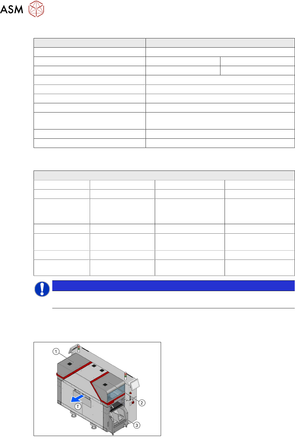
2.2 Machine Overview
General Overview
T - Transport direction
1. Location 1
2. Location 2
3. COT for location 2
2 Machine Basic Overview
2.2 Machine Overview
Technical Training FSE SIPLACE TX-Series 01/2018 15
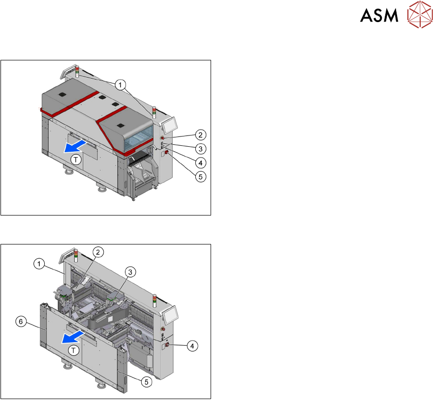
Machine Switches
T - Transport direction
1. Status lamp
2. E-Stop
3. Start / Stop button
4. Switch to dock / undock COT
5. Main switch
Main Component Locations
T - Transport direction
1. Vacuum pump location
2. Gantry 1
3. Gantry 2
4. Switch Mode Power Supply Location 2
5. Pneumatic unit
6. SIPLACE LAN and transport interface con-
nections, power in