00198171-02_Technical_Training_FSE_TX-Series_EN.pdf - 第38页
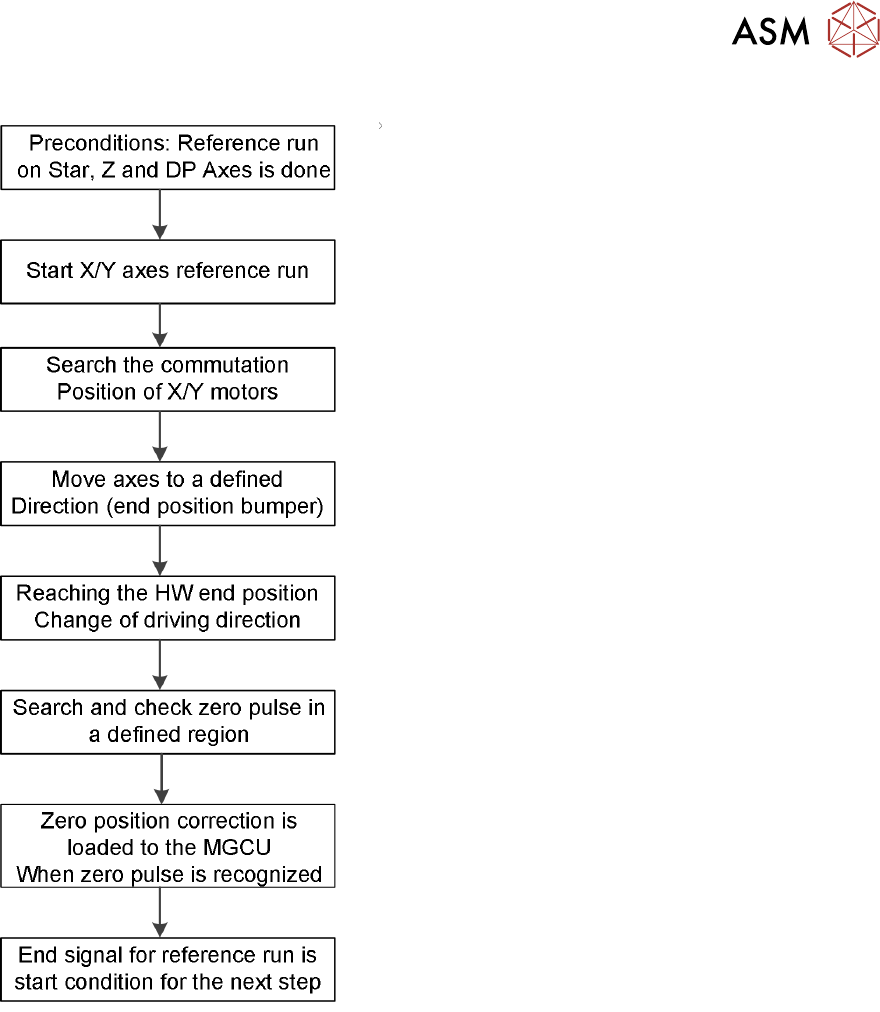
4 Gantry System 4.2 Reference Run 38 Technical Training FSE SIPLACE TX-Series 01/2018 Reaching the HW end position, change of driving direction and finding the zero pulse After the commutation search, the motor is in an …
4 Gantry System
4.2 Reference Run
Technical Training FSE SIPLACE TX-Series 01/2018 37
Reference Run Workflow
Reference Run detailed Workflow
Preconditions: Axis reference run must be successfully completed for the relevant placement
heads.
Commutation position search for 3 phases AC-drives on gantry during initial reference run:
1. Two motor phases are switched by the MGCU.
2. The 3-phase AC motor moves to the next suitable magnetic position.
3. Two other motor phases are switched by the power supply and the axis moves further.
4. These switching steps are repeated multiple times.
5. The axis reference run is continued with a reference position search for the position measur-
ing system.
4 Gantry System
4.2 Reference Run
38 Technical Training FSE SIPLACE TX-Series 01/2018
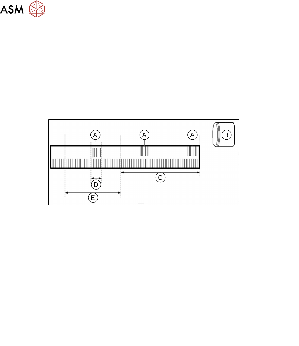
Reaching the HW end position, change of driving direction and finding the zero
pulse
After the commutation search, the motor is in an undefined position for the control system.
1. Referencing with bumper recognition (hardware end stops), the axis moves successively
against the bumpers. This is done using fixed target values set by the axis controller, these
are increasingly closer to the mechanical end stop.
2. After a some time, the axis reaches a state in which the set target position is no longer
reached (actual position ≠ target position), the axis is at the hardware end stop (bumper).
3. After reaching a certain motor current (approx.10ms later) the direction of travel is reversed
and the axis searches for the zero pulse within a specified range. The motor is now in posi-
tion control.
A
B
C
D
E
Zero pulse
Bumper
No searching area for the zero pulse configurable
Area to check the right zero pulse
Searching area for zero pulse configurable
4. The search for a zero pulse is prohibited within a certain distance from the bumper (approx.
25mm).
5. After moving out of this prohibited area, the search begins. If the zero pulse is found in this
area, further pulses will be searched for in an area of approx. 2.5 mm. If only one zero pulse
is found, an end position message is issued and the reference run is completed.
6. In the event of a fault (multiple zero pulses or no zero pulses in the defined area) the axis will
stop and an error message will be issued.
7. The axes are now in a defined position. After finding and checking the zero pulse, the zero
point correction is loaded.
8. The reference run for the main axes has now been completed.
9. The vacuum and height reference runs will begin.
The reference run for the main axes is started simultaneously at all gantries.
TX micron gantry differences
●
X/Y glass scale thermal stable Robax-scales (glass-ceramic composite) for gantry system
with highest resolution of 10nm.
●
Encoder interpolate 20um
– X-Encoder TXm MS30
– Y-Encoder TXm MS30
●
Two sensor modules mounted on the X-Axis which convert the analog X and Y track signals
in to digital signals.

4 Gantry System
4.3 Calibration after Repair and Adjustment
Technical Training FSE SIPLACE TX-Series 01/2018 39
4.3 Calibration after Repair and Adjustment
4.3.1 Explanation of main Gantry Calibrations
Zero point offset (machine Zero Point Correction)
The machine ZPC (station point for each gantry) is used as point of reference for the X/Y Axis to
the machine coordinate system. Thus the axes know their current positions in the machine. The
PCB camera moves towards this machine zero point (fiducial). Then the X/Y directions are meas-
ured. The resulting offset is taken into account in the fixed zero point correction of the X/Y Axis.
Travel range
The axis concerned moves as far as possible towards the minimum or maximum position and the
limit is set.
System identification
Checks the controls parameters of the X/Y Axis to ensure reliable control of the axis movement.
The procedure should be repeated if the machine has been moved or if gantry conversion has
been done.
X Axis parametrization
Optimizes the X Axis control parameters.
Board camera (PCB camera)
Determines the calibration factors, the relation of the camera pixel size to the resolution of the
machine measurement system (X, Y) and the mounting angle of the CCD sensor in the PCB cam-
era.