00198171-02_Technical_Training_FSE_TX-Series_EN.pdf - 第45页
4 Gantry System 4.6 Analyze Technical Training FSE SIPLACE TX-Series 01/2018 45 4.6 Analyze Code Error description Possible cause Action 30362 30470 30471 X/Y Axis counting error during reference run ● Dirty scale ● Dirt…
4 Gantry System
4.5 Control and Communication Overview
44 Technical Training FSE SIPLACE TX-Series 01/2018
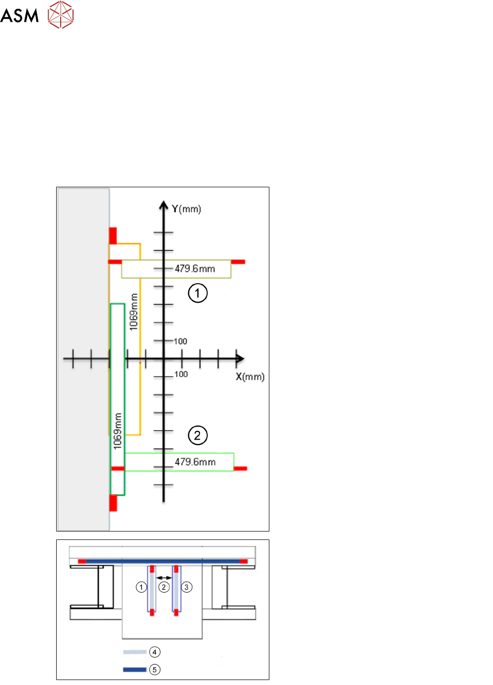
4.5.1 Gantry System - Travel Ranges and Speed Monitoring
Travel ranges and speed monitoring
The travel range of the X/Y Axis will be determined during machine calibration.
●
The end of the X Axis travel range is + or - 0.5 mm before the software limit switch, which is
1.5 mm before the buffer. A safety distance of 2.0 mm to the buffer is adequate if the X Axis
moves into this area with excessive speed.
●
The end of the Y Axis travel range is + or - 2.0 mm before the software limit switch. The Y
Axis travel range for a particular placement area is monitored in one direction by the software
limit switch and a buffer. In the other direction, there is a permanent exchange of communica-
tion between the axes and their positions.
1. Gantry 2
2. Gantry 1
1. Gantry 1
2. Safety distance between the gantries dur-
ing placement. Minimum: 4mm
3. Gantry 2
4. Travel range X
5. Travel range Y

4 Gantry System
4.6 Analyze
Technical Training FSE SIPLACE TX-Series 01/2018 45
4.6 Analyze
Code Error description Possible cause Action
30362
30470
30471
X/Y Axis counting error
during reference run
●
Dirty scale
●
Dirty encoder
●
Wrong reader position
●
Defect reader/scale
●
Clean scale
●
Clean encode reader
●
Adjustment distance
between encode reader and
scale
●
Change encode reader and
adjustment
●
Check/change scale
●
Calibration of ZPC, travel
range after adjustment of
reader
30562
30468
33522
Gantries too close to
each other
Distance too close between
two gantries or two gantries
touched
Move one gantry away from the
other and conduct reference run
4.7 Main Parts Exchange / Setting / Calibration
Overview of the parts which require adjustment after exchange. For detailed information refer to the
service manual.
Gantry parts exchange Tools/ Setting Calibration
X Axis incremental encoder Distance from scale:
0.75 ± 0.2mm
Travel range and machine ZPC
Y Axis incremental encoder Distance from scale:
0.75 ± 0.2mm
Travel range and machine ZPC
Head plate temperature sensors Head and camera
The PCB camera
●
Machine ZPC
●
Board camera
●
Head and camera offset
Y Axis buffer Travel range
X scale Adjust encoder as above Travel range and machine ZPC
Y scale Adjust encoder as above Travel range and machine ZPC
Head adapter for the MHCU Switch adjustment Check/download eSW (firmware)
Head interface PCB Switch adjustment
To remove the air hoses an unlocking tool is required 03051853.
4.8 Gantry System and Base Machine - Overview
Maintenance
Maintenance item for base machine, for detail see maintenance job card.
Maintenance content Interval Equipment required
Magnetic surfaces of X/Y Axis All workflows Cleaning wipe
Clean gantry cables All workflows Cleaning wipe
X/Y Axis guidance rail All workflows SIPLACE tissue
X/Y Axis scale Workflow 2 Cleaning wipe, ethyl alcohol
IC camera for CPP/TH Workflow 2 Cleaning wipe
Head exhaust air filter Workflow 3 Air gun, Allen key
4 Gantry System
4.9 Excercise: TX Gantry System
46 Technical Training FSE SIPLACE TX-Series 01/2018
Maintenance content Interval Equipment required
Compressed air filter Workflow 3 Air gun
Vacuum pump filter Workflow 3 Air gun, Allen key
Gas pressure shock absorber Workflow 4 Cleaning wipe
Linear guide bearing of X/Y Axis Workflow 4 Kluber oil BEM 34-132 cartridge
Protection covers Workflow 4 Cleaning fluid for the covers
Magnetic surfaces of X/Y Axis All workflows Cleaning wipe
4.9 Excercise: TX Gantry System
1. Which of the following is false regarding the TX Gantry system?
A The head interface board for Gantry 1 and 2 can be exchanged (swapped over).
B Both X and Y Axes are driven by linear motors.
C The TX gantry reference run is the same with X-Series S machine.
D MGCU is used for X and Y motor control.
2. Which action should be performed after exchange of the Y Axis encoder reader?
A Adjust the distance (0.75mm) between encode reader and scale.
B Calibrate travel range for both gantries.
C Calibrate machine zero point.
D All of the above.
3. Describe the machine reference run.
………………………………………………………………………………………………………
………………………………………………………………………………………………………
………………………………………………………………………………………………………
………………………………………………………………………………………………………