00198171-02_Technical_Training_FSE_TX-Series_EN.pdf - 第54页
5 Component Supply 5.5 Reject plate on TX 54 Technical Training FSE SIPLACE TX-Series 01/2018 5.5 Reject plate on TX The reject plate is an option for TX1 and TX2 machine for location 1. Components with vision er- rors c…
5 Component Supply
5.4 Tape Cutter
Technical Training FSE SIPLACE TX-Series 01/2018 53
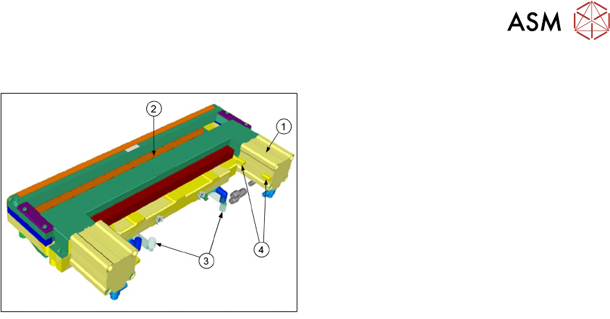
5.4 Tape Cutter
1. Pneumatic cylinder
2. Slot for empty tape
3. Magnetic valves
4. Proximity switch
On both sides of the tape cutter are pneumatic cylinders which activate the blade by alternating
movements. Two solenoid valves (24V / 5.1 bar) controlled by FCU.
The tape cutter is activated when the gantry moves to the first placement position, alternating one
of the cylinders start to front position.
●
Once the first cylinder reaches the front position, the second cylinder is started.
●
Both cylinders are withdrawn at the same time.
●
The cutter will be actuated once after each placement cycle of relevant placement head.
The tape cutter can be removed in about 15 minutes for service purposes. The throttle timings
need to be set. For detailed information about dismantling and settings refer to the service manual.
5 Component Supply
5.5 Reject plate on TX
54 Technical Training FSE SIPLACE TX-Series 01/2018
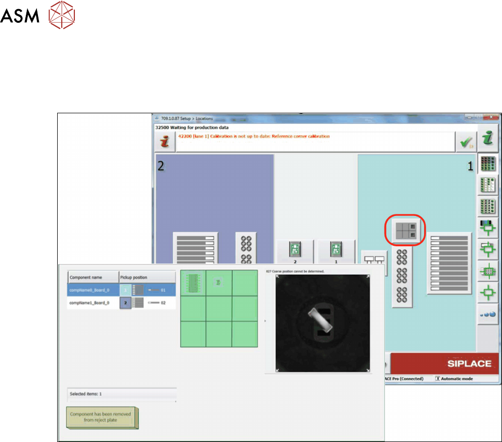
5.5 Reject plate on TX
The reject plate is an option for TX1 and TX2 machine for location 1. Components with vision er-
rors can be placed on the reject plate instead of being rejected to the reject bin.
The following information of the rejected components on the reject plate will be showed:
●
Position of the component on the reject plate
●
Pickup position from where the component was picked up.(if a component was picked up from
a tray, only the level and magazine number are shown, but not the pickup position in the
magazine!)
●
Related vision dump
●
Component name
●
Component shape
If the reject plate has been fitted, it will need to be configured in the station software.
This option has to be enabled in SIPLACE Pro for the respective component / component shape.
The removal of the component from the reject plate can be confirmed with the button "Component
has been removed from reject plate". Confirmation has to be done for each component.
5 Component Supply
5.6 Component Supply Pneumatic & Electrical System
Technical Training FSE SIPLACE TX-Series 01/2018 55
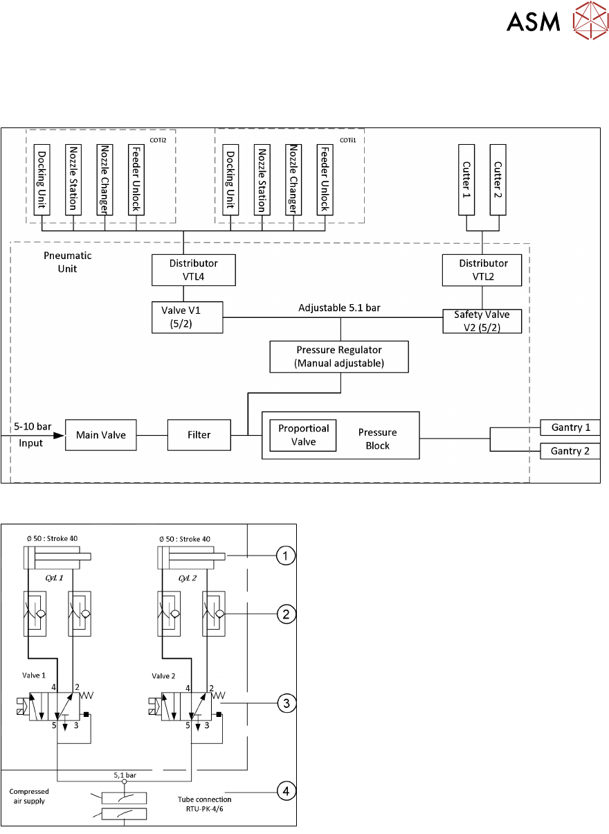
5.6 Component Supply Pneumatic & Electrical System
5.6.1 Overview Pneumatic System
Tape Cutter Pneumatic System
1. Drive cylinder for cutter blade movement
40mm stroke
2. Adjustable throttle valve on the pneumatic
cylinder. Timings can be checked in the
station software. See service manual for
details
3. 5/2 way magnetic valve
4. 5,1 bar compressed air supply
Cutter only active if control system on.