00198171-02_Technical_Training_FSE_TX-Series_EN.pdf - 第95页
7 Power Supply 7.3 Voltage Overview Block diagrams Technical Training FSE SIPLACE TX-Series 01/2018 95 Fuse F11 - F13 Voltage Type Fuse Usage 24 VDC Switched F11 Supply voltage for safety relays (CSB) 24 VDC Switched F12…
7 Power Supply
7.3 Voltage Overview Block diagrams
94 Technical Training FSE SIPLACE TX-Series 01/2018
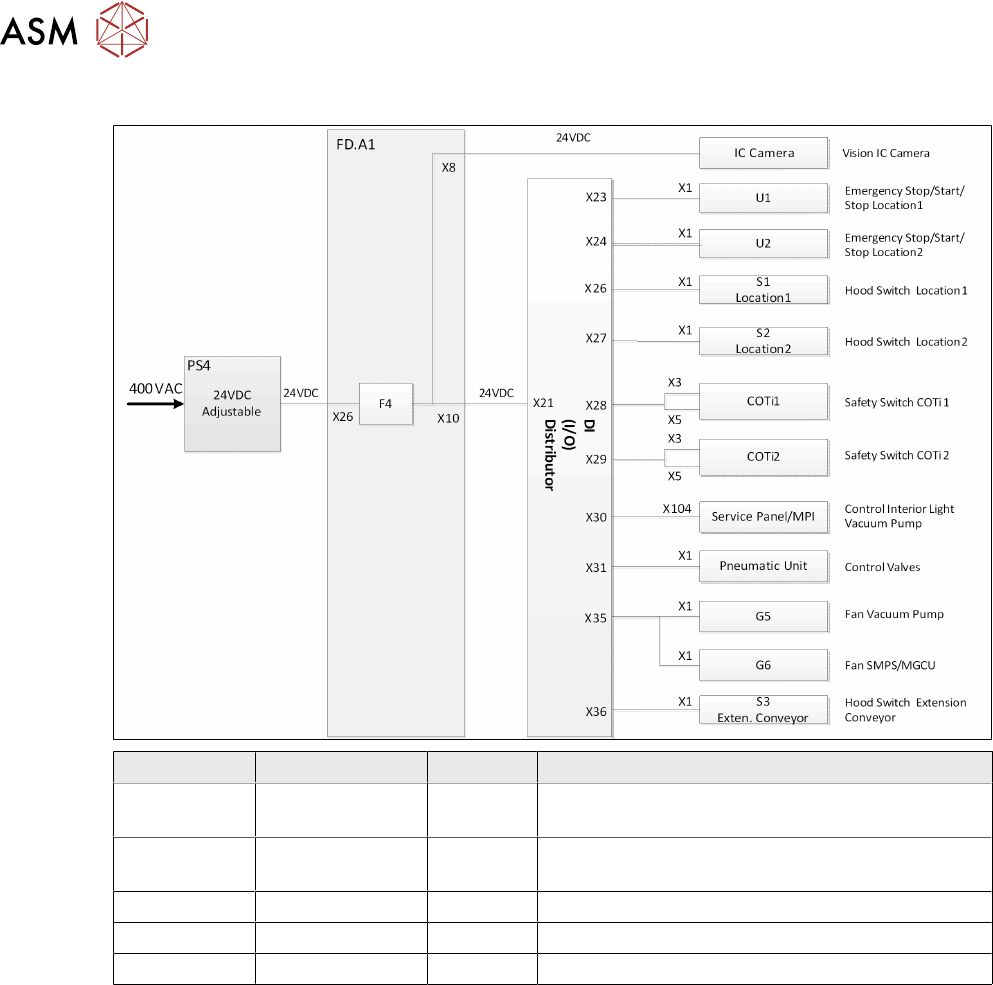
Fuse 4
Voltage Type Fuse Usage
24 VDC Unswitched F4 Supply safety (emergency stop ,safety switches
Start/Stop buttons…) loop
24 VDC Unswitched F4 Supply pneumatic unit (proportionate valve/ main
pressure valve)
24 VDC Unswitched F4 Supply emergency STOP button R/L
24 VDC Unswitched F4 Supply safety switch tables 1/2
24 VDC Unswitched F4 Supply voltage vision (IC camera)
7 Power Supply
7.3 Voltage Overview Block diagrams
Technical Training FSE SIPLACE TX-Series 01/2018 95
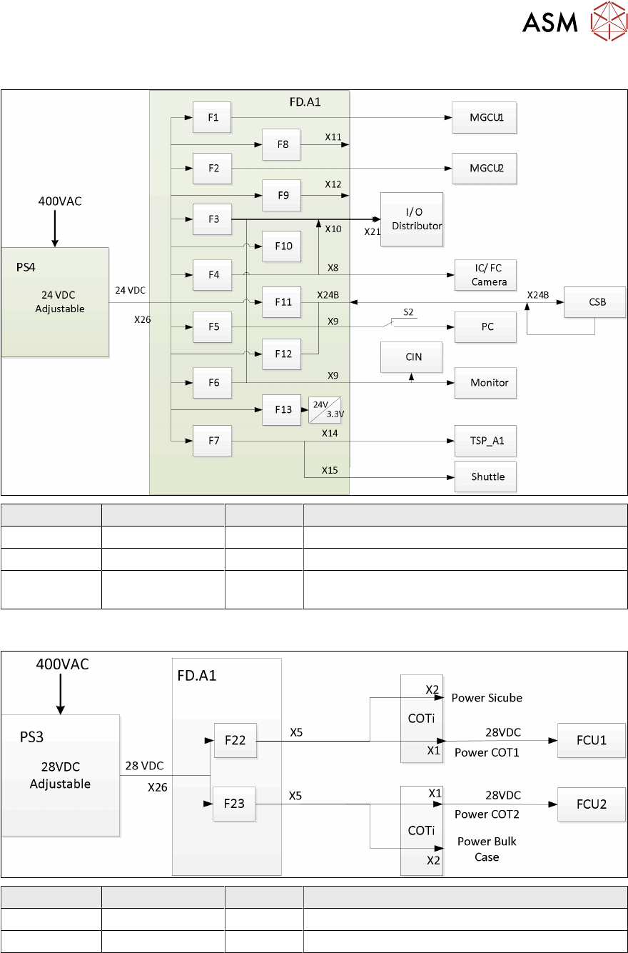
Fuse F11 - F13
Voltage Type Fuse Usage
24 VDC Switched F11 Supply voltage for safety relays (CSB)
24 VDC Switched F12 Internal supply voltage for safety control
24 VDC Unswitched F13 Internal supply voltage for diagnostic FD.A1
(24V/3.3V)
7.3.6 28 VDC Unswitched
Voltage Type Fuse Usage
28 VDC Unswitched F22 Supply Voltage FCU Location 1 (min 26.8V)
28 VDC Unswitched F23 Supply Voltage FCU Location 2 (min 26.8V)
If the PS3 is not correctly set to 28 VDC (min output voltage 26.8V) the FCU will not function reli-
ably!
7 Power Supply
7.4 CAP Function Description
96 Technical Training FSE SIPLACE TX-Series 01/2018
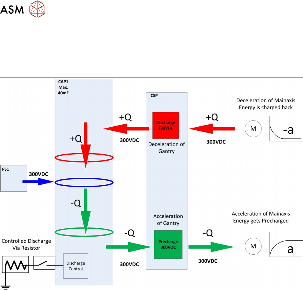
7.4 CAP Function Description
If energy is needed to accelerate the axes (gantry jump), energy is taken from the capacitor battery
(CAP) (pre-charge 300VDC/ -Q)
During braking, the braking energy is fed back by the motors and recharged into the backup battery
(+Q), in a controlled state via the discharge control (discharge 300VDC).