00198171-02_Technical_Training_FSE_TX-Series_EN.pdf - 第98页
7 Power Supply 7.6 Function Description of Individual Assemblies SMPS TX 98 Technical Training FSE SIPLACE TX-Series 01/2018 7.6 Function Description of Individual Assemblies SMPS TX 7.6.1 Main switch The main switch is …
7 Power Supply
7.5 Overview of Fuse board FD:A1
Technical Training FSE SIPLACE TX-Series 01/2018 97
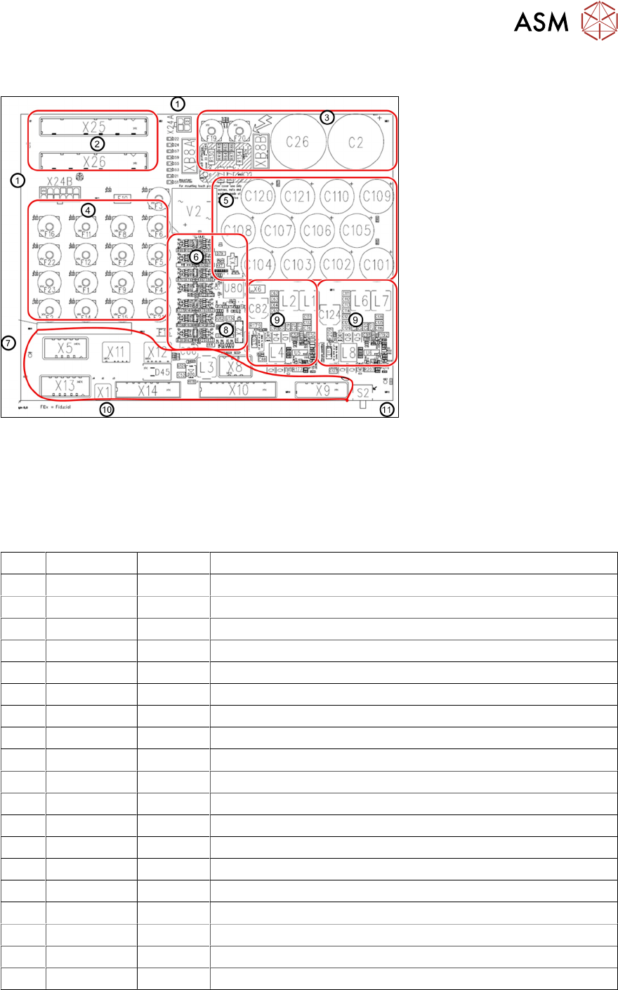
7.5 Overview of Fuse board FD:A1
1. Connector to CSB unit 5. 42V head buffer caps 9. Head Boost converter in-
put 42VDC output
25,5VDC
2. Low voltage input 6. Diagnostic unit
3. Buffer capacitor ,160VDC 7. Output voltages connectors 10. PE connection
4. Low voltage fusing array* 8. Diagnostic data connector 11. Box PC voltage switch
*Fuse types: FUSEHD PCB (5X20MM Vertical)
F1 24 V DC 6.3A MGCU1
F2 24V DC 6.3A MGCU2
F3 24 V DC 6.3A Service
F4 24 V DC 6.3A Distributor Power Fail
F5 24 V DC 6.3A IBASE PC
F6 24 V DC 6.3A Option 3D co-planarity PC
F7 24 V DC 6.3A Conveyor
F8 24 V DC 6.3A Gantry 1
F9 24 V DC 6.3A Gantry 2
F10 24 V DC 0.5A Internal – power fail (internal CSB)
F11 24 V DC 6.3A SSK_Ready
F12 24 V DC 6.3A Safety supply CSB
F13 24 V DC 3A SMD Internal fuse 24V diagnosis replace PCB if defect
F14 42 V DC 6.3A Gantry cable 1 HCU 25,5V converted from 42V
F15 42 V DC 6.3A Gantry cable 2 HCU 25,5V converted from 42V
F16 42 V DC 10A Conveyor drives
F19 160 V DC 6.3A Head axes gantry 1
F20 160 V DC 6.3A Head axes gantry 2
F22 28 V DC 6.3A FCU1
F23 28 V DC 6.3A FCU2
7 Power Supply
7.6 Function Description of Individual Assemblies SMPS TX
98 Technical Training FSE SIPLACE TX-Series 01/2018
7.6 Function Description of Individual Assemblies SMPS TX
7.6.1 Main switch
The main switch is combined with a motor protection switch with combined trip block.
It is approved as a mains breaker device, main switch and protective switch.
The trigger current for the protective switch does not need to be set, however depending on usage
there are 2 different types of motor switch.
●
Standard: Main circuit breaker 3~380-415V: 03125553-(6.3A)
●
Low voltage countries: Main circuit breaker: 3RV27 3 pole 03138992-(12,5A, UL489)
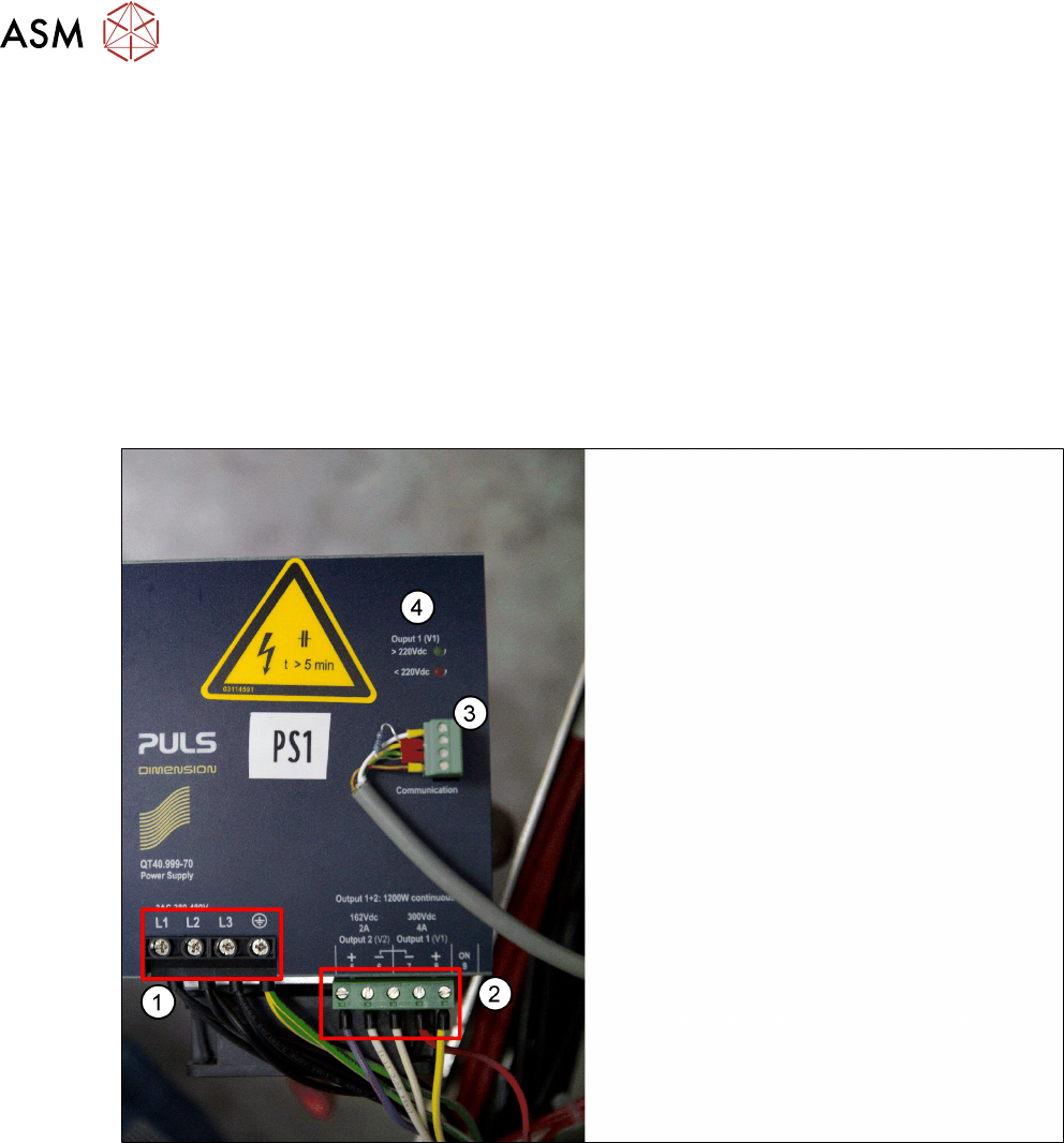
7.6.2 Power Pack PS1-(330 VDC/ 160 VDC)
1. Input Connection 3 phase AC
2. Output 300 VDC/ 160 VDC
3. Diagnosis connector
4. LED for displaying residual voltage
●
The 300VDC voltage is used for the main axis drives. Due to the high current peaks, this
voltage needs to be buffered at the output end.
●
The buffering of the 300VDC voltage is realized with the CAP1 backup battery.
●
A pre/discharge control function on the pre/discharge board A2 is used for controlled energy
release (during acceleration) and energy absorption (during braking) by the backup battery for
the main axes.
●
The 160VDC voltage is used for the head axes. Once again, the high current peaks require
backup storage at the output end.
●
The backup storage of the 160VDC voltage takes place on the pre/discharge board -A2 with
the help of capacitors.
7 Power Supply
7.6 Function Description of Individual Assemblies SMPS TX
Technical Training FSE SIPLACE TX-Series 01/2018 99
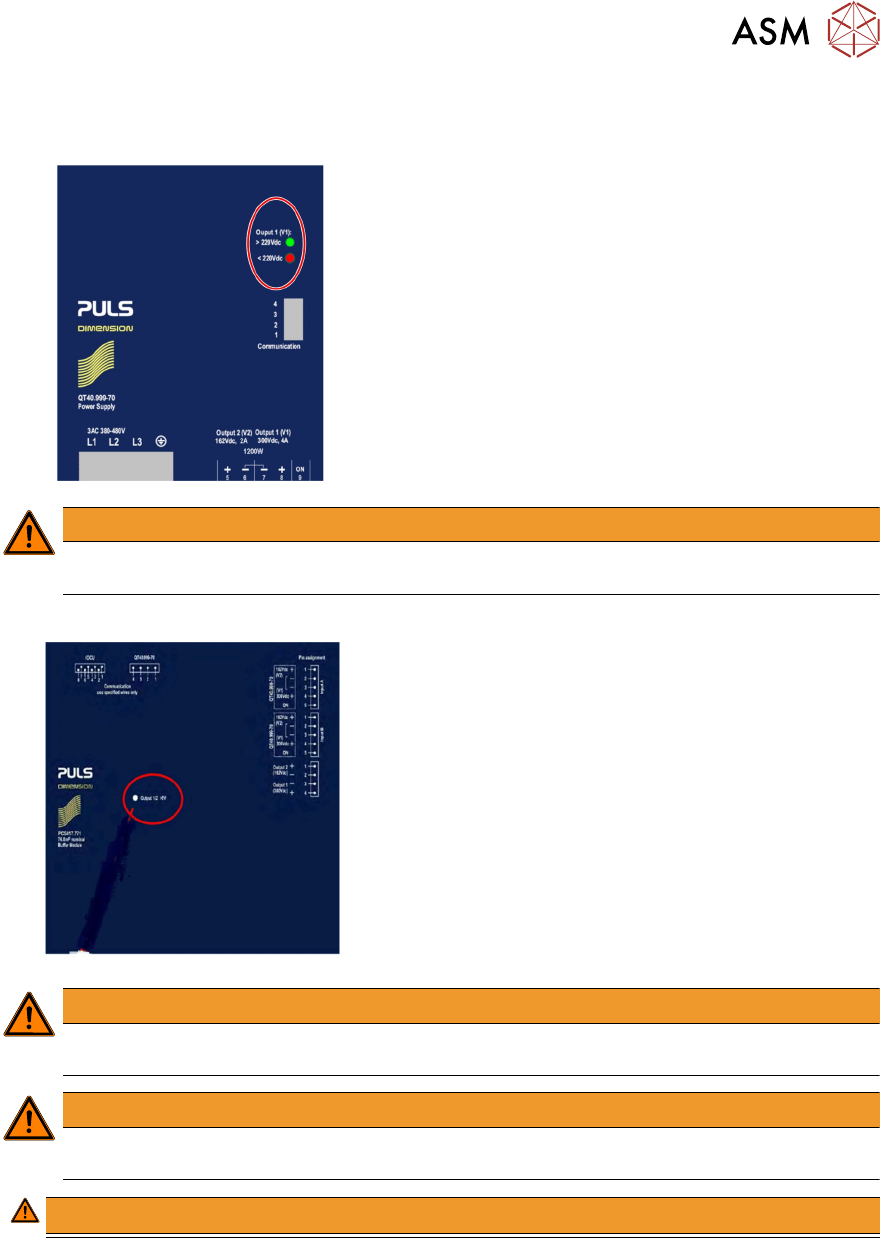
7.6.2.1 Power Supply(SMPS) – Safety Indication
Lamp indication on PS1
●
LED Green 300VDC to 220VDC
●
LED Red 220VDC to 5VDC
●
LEDS Off less than 5VDC
WARNING
Only after the voltage dropped <5VDC (both LED lamps off) can you work on the power
supply unit without hazard!
Lamp indication on CAP1
●
LED Red greater than 5VDC
●
LED Off less than 5VDC
WARNING
Only after the voltage dropped <5VDC (LED lamp off) can you work on the CAP1 unit
without hazard!
WARNING
The LED status do not grantee that the units are free from voltage it is always necessary to
measure the voltage before commencing service work.
WARNING!
.