5OM-1626-001_w.pdf - 第123页
5OM-1610 4-8 091 1-001C(M913W A---0001) Integrated Blaock Connection Diagram A B C D 24C 24C 24F 24F 24F 24F 24F 24F 24F 24G* 24G* 24G5A 24G8A 24G1,2A 24G1,2B 24G5B 24G8B 24B3 24B1 24B1 24A2 24B1 24B1 24B1 24B1 24B1 24B1…
5OM-1610
4-70911-001
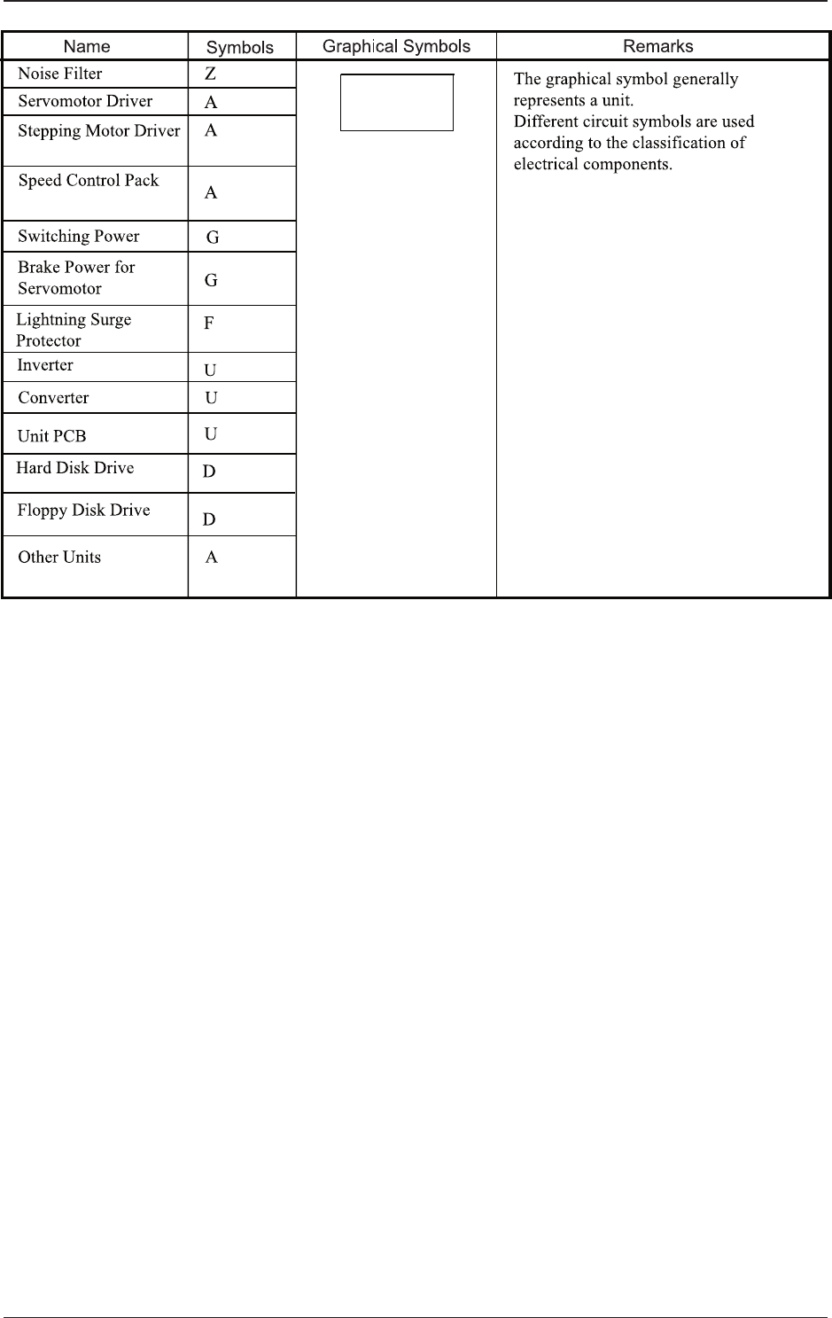
Electrical and Electronic Symbols
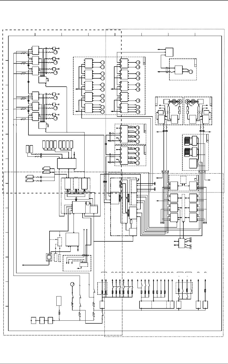
5OM-1610
4-80911-001C(M913WA---0001)
Integrated Blaock Connection Diagram
A
B
C
D
24C
24C
24F
24F
24F 24F
24F
24F
24F
24G*
24G*
24G5A
24G8A
24G1,2A
24G1,2B
24G5B
24G8B
24B3
24B1 24B1
24A2
24B1
24B1
24B1 24B1
24B1
24B1
24B1
24B2
24B1
24B3
24B4
24B2
5J1
48D3A
48D3B
48D3E
48H
48D3G
48D3F
48D3K
48D3J
48D3K
48D3H
48D3F
48D3H
48D3E
48D3G
48D
48D3A 48D3B
48H
5J
24A*
24A1
24A3
24A3
24A1
24A1
24A2
24A0
24A3
3
3
22
3
3
2
3
3
3
2
3
M MM M
MMMM
MM MMM MMMM
MMMM MMMM
M
MM
3
M
3
M
3
M
3
M
3
M
3
M
3
M
F201~203
F200
Q201
Q204
K28
Q205
K29
M66
Q206
+48V(D)
G2
F13
F14
F33
K38
U27
CONTROL
U82
MOTION
U85
HLSC
RS485
I/OSSCNET
U81
CPU
COM1 LAN
AC-IN
+5V
HLS LINK (HEAD)
HLS LINK
HLS LINK (IF+HEAD)
HLS LINK
SERIAL
SERIAL
I/O
ID:0
D81
A21R
Servo Motor
A22R A23R
M21R
X-Axis
Linear Scale
I/F
U21R
M22R
U22R
M23R
U23R
AMP
Y1-Axis
Linear Scale
Y2-Axis
Linear Scale
Servo Motor
AMP
Servo Motor
AMP
I/F I/F
CN5
U24R
Connector
PCB ENCD
Q221R Q222R Q223R
A21F
Servo Motor
A22F A23F
M21F
X-Axis
Linear Scale
I/F
U21F
M22F
U22F
M23F
U23F
AMP
Y1-Axis
Linear Scale
Y2-Axis
Linear Scale
Servo Motor
AMP
Servo Motor
AMP
I/F I/F
CN5
Connector
PCB ENCD
Q221F Q222F Q223F
M63F
CT-Axis
U
CU-SRS
NOISE
FILTER
Z02
NOISE
FILTER
Z01
Q200
K33A
LAN2
CPU
U91
USB(1)
VGA
LAN1
USB(2)
124
124
U92
Frame
Grabber
PIO
CAM
+12V
AC-IN
CPCI
PCI
124
U93
Frame
Grabber
PIO
CAM
124
U94
COUNTER
IN
OUT
CN2
CN3
CN1
U95
CN6
CN8
CN5
CN7
E191
B61(1)
B61(2)
(2)
CN4
U178
USB HUB
FRONT
N74
N76
N75
Option
(300W)
(100W)
Option
F43
U
DL-SRS
NA-BAL
M53
A53
CN9
EMG
CN10
PWR
N2
AE
N1
AE
CN5CN1
M54
NA-BAR
CN12 CN12
2CH1CH
2CH1CH
U181F
CN1 CN4 CN2
A63F
Servo Motor
AMP
CN2CN1
CN3 CN5
K10
F29
F30
CH1 CH2
A_LINK
AE_LINK
U24F
AE LINK
AE LINK
E192
(2)
E193
(2)
E194
(2)
E191
(1)
E192
(1)
E193
(1)
E194
(1)
COM2
G21
G22
COM1
COM2
+5V
F34
F44
K50
K33B
CN7CN3
NA-LB1
M47
A161
CN9
EMG
CN10
PWR
N2
AE
N1
AE
CN5CN1
M48
NA-LB2
CN7CN3
NL-LB1
M45
A47
CN9
EMG
CN10
PWR
N2
AE
N1
AE
CN5CN1
M46
NL-LB2
CN7CN3
NA-W1
M161
A45
CN9
EMG
CN10
PWR
N2
AE
N1
AE
CN5CN1
M163
NA-W3
CN7CN3
NL-LA1
M41
A41
CN9
EMG
CN10
PWR
N2
AE
N1
AE
CN5CN1
M42
NL-LA2
CN7CN3
NA-BBL
M55
A55
CN9
EMG
CN10
PWR
N2
AE
N1
AE
CN5CN1
M56
NA-BBR
CN7CN3
NA-LA1
M43
A162
CN9
EMG
CN10
PWR
N2
AE
N1
AE
CN5CN1
M44
NA-LA2
CN7CN3
NA-W2
M162
A51
CN9
EMG
CN10
PWR
N2
AE
N1
AE
CN5CN1 CN7CN3
NR-LA1
M49
A49
CN9
EMG
CN10
PWR
N2
AE
N1
AE
CN5CN1
M50
NR-LA2
CN7CN3
NR-LB1
M51
A43
CN9
EMG
CN10
PWR
N2
AE
N1
AE
CN5CN1
M52
NR-LB2
CN7CN3
ILB
U05
U27
(1) (2)
CN3
CN4
CN1
CN2
CN1
CN4
CN5
CN3
CN4
CN3
CN4
HLS LINK
HLS LINK
SERIAL
Relay P.C.B
(1) (2)
PWR
U12
CN3
CN4
CN3
CN4
U01
CN3
CN4
CN1
CN2
PNL
CN3
CN4
CN1
CN2
CN1
CN2
CN1
CN2
CN1
CN2
CN1
CN2
D91
U
SL-SRS
(F)
K52
(RS232C)
U190
FB
U69
CN9
CN8
CN6
U
FB-SRS
U68a
X100
Connector PCB
U68b
X100
Connector PCB
FEEDER
FEEDER
E39
E39
(1)
(2)
B36(1)
B36(2)
(R) (F) (R) (F)
NSDD
M32M31
Servo Motor AMP
A31
CNP1
48V/24V
CN1A
SSC
CN3
24V
NSDD
M32M31
A31
Servo Motor AMP
U
HH-SRS(2)
CN1B CNP1
48V/24V
CN1A
SSC
CN3
24V
CN1B
U
HH-SRS(1)
P2A 2A P2B 2B P2C 2C P2D 2D P2A 2A P2B 2B P2C 2C P2D 2D
+3.3V
+5V
+5V
+12V
U180
U25
X1
LINE SENSOR
U03
CN6
CN5
X2
Slip
LINE SENSOR
U03
U147
Conn.
CN1
X1
U25
X2
CN1 CN6
CN5
Rings
U37
Slip
J1
Rings
U37
U04
U04
U
HH-SRS(1)
U
HH-SRS(2)
P.C.B
U147
Conn.
P.C.B
J1
AE LINK
AE LINK
CH2CH1
X18514X18512
(CN8) (CN5)
CN1
(CN9) (CN10) (CN13) (CN15)(CN3)(CN14)
2 3 412 3 41
U07 U08
U06
CNVR-L
CUT(2)
U14
CNVR-R
U09
CUT(1)
IF
Stepping Mot AMP Stepping Mot AMP Stepping Mot AMP Stepping Mot AMP Stepping Mot AMP
Stepping Mot AMP Stepping Mot AMP Stepping Mot AMP Stepping Mot AMP Stepping Mot AMP
M33
NL
M34
HL
M33
NL
M34
HL
U72
HUB
CPUM-OUT:LAN1
CPU1-LINE:LAN1
CPUM-LINE:LAN2
+24V(G)
G4
+24V(A)
G1
+24V(B)
+24V(C)
+24V(F)
F1
K1A
F42
+48V(F)
G7
F2
F5
K25
F7
F52
F41
K75
K71
K77
K72
K1B
F21-24
F25-28
U27
U165
VGA-OUTPUT
VGA2
DC-IN
VGA1
+5V(J)
G8
F61
LCD
(TP)
DOM
DOM
A31:
A41,A45,A47:
A161,A53:
A43,A49,A51:
SV-NET
A63R:
A63F:
A162,A55:
INPUT
A31:
U95:
OUTPUT
U72:HUB
OUTPUT
Image Distributor
U165:
(OP)
1
2 3 4 5 6 7 8 9 10 11 12
A
B
C
D
E
F
G
H
Lighting Surge
Protector
Vacuum Pump
Main Power
Supply
Control Power
Supply
Main Power Unit for the Head Unit
Multi-axis Board
Main Power Unit for the Transfer Unit 2-Axis Board
Safety Circuit
N74: Power Unit for the Front and Rear Monitors
External Power Unit for the Input and Output Machines through I/F
Head Unit Multi-Axis Board Control Power Unit
Main Power Unit for the LED Lighting Control PCB
Power Input Circuit
Safety Circuit
U71:CPU_M(OP)
Main Power Unit for the Transfer Unit 2-Axis Board
Power Unit for the Transfer Unit 2-Axis Board
Track Ball
Key Board
CT Axis SV-NET Power Supply
CT Axis SV-NET Power Supply
Main Power Unit for the Transfer Unit 2-Axis Board
To be attached
externally to the Machine
Out side AN
other SIGMA
CPU1
other SIGMA
CPU1
Cooling Fan
External Unit
Connecting Bundled
Connector
Beam Connector
Relay Panel
Power Unit for the External Unit (1)
Power Unit for the External Unit (2)
External LAN Connection Panel
Image Changer
CPU1 (Operation and Recognition PC)
LED Lighting
Control PCB
PEC Recognition Lighting
PEC Recognition Lighting
ATX Power Supply
PEC Recognition Lighting
Power
Supply
PEC Recognition Camera
Component
Recognition
Camera
Beam Connector
Relay Panel
Trigger
Beam Connector
Relay Panel
ATX Power Supply
Power
Supply
CPU2 (Control PC)
SSCNET3 (Optic)
SSCNET3 (Optic)
SSCNET3 (Optic)
Beam Connector
Relay Panel
Beam Connector
Relay Panel
External Unit Connecting
Bundled Connector (Rear)
External Conver Connection Panel
(Left) (Right)
Each Loads
and Sensor
External Unit Connecting
Bundled Connector (Front)
15 Lane 15 Lane
Beam Connector
Relay Panel
LINE SENSOR
LINE SENSOR
Beam Connector
Relay Panel
Light
Reception
Light
Emission
Light
Emission
Light
Reception
Converter
External Unit Connecting
Bundled Connector
Note 1
Beam Connector
Relay Panel
Beam Connector
Relay Panel
Main Power Supply
Control Power Supply
SSCNET3 (Optic)
Each Loads and Sensor
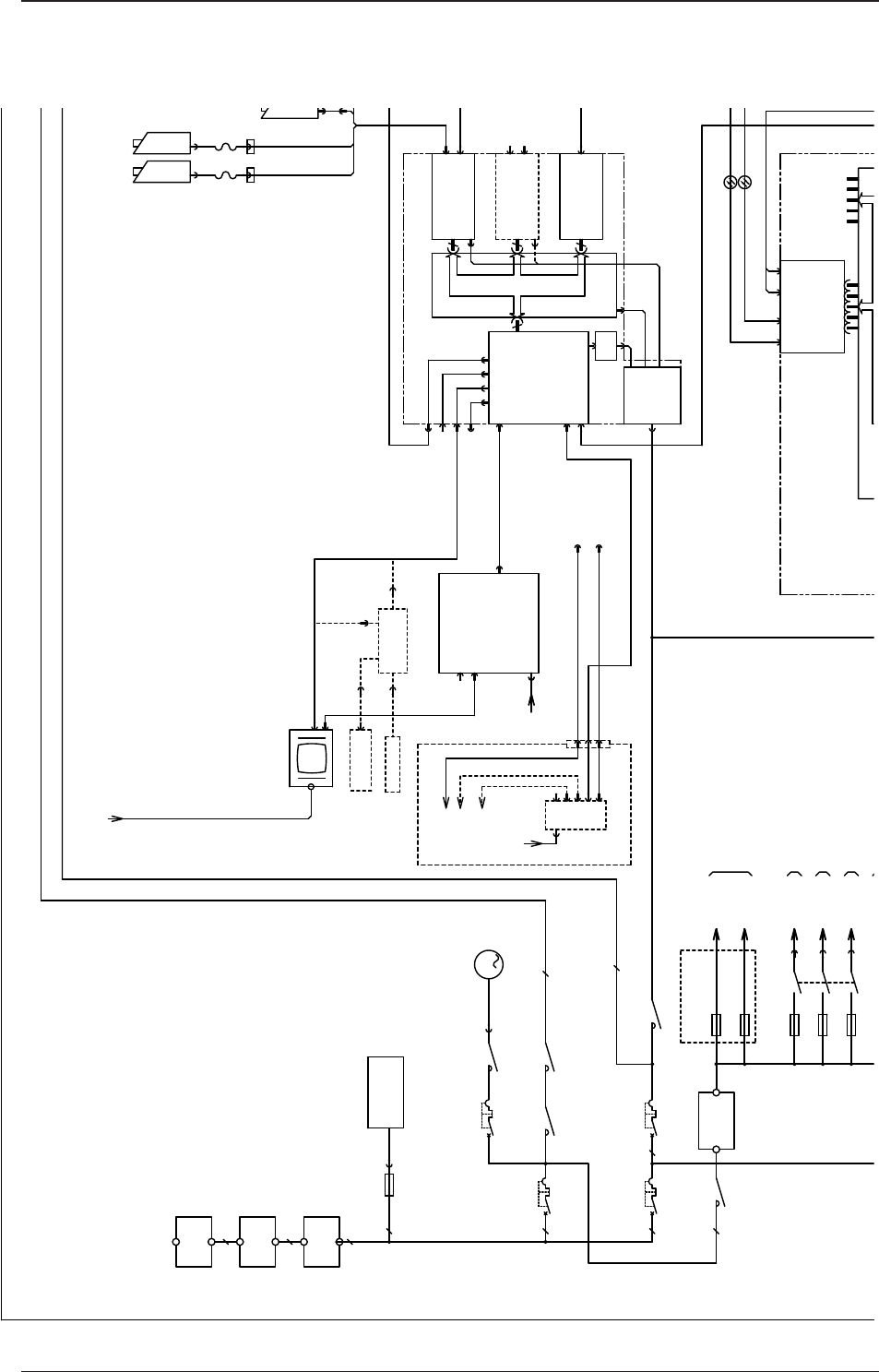
5OM-1610
4-90911-001C(M913WA---0001)
Integrated Block Connection Diagram (Details A)
24B3
24B2
5J1
48D3A
48D3B
48D3E
48D3G
48D3F
48D3H
3
3
22
3
3
3
3
2
3
3
M
F201~203
F200
Q201
Q204
K28
Q205
K29
M66
Q206
+48V(D)
G2
F13
F14
F33
K38
U27
CONTROL
U82
MOTION
I/OSSCNET
ID:0
NOISE
FILTER
Z02
NOISE
FILTER
Z01
Q200
K33A
LAN2
CPU
U91
USB(1)
VGA
LAN1
USB(2)
124
124
U92
Frame
Grabber
PIO
CAM
+12V
AC-IN
PCI
124
U93
Frame
Grabber
PIO
CAM
124
U94
COUNTER
IN
OUT
B61(1)
U178
USB HUB
FRONT
N74
N76
N75
Option
(300W)
Option
F43
2CH1CH 2CH1CH
K10
G21
COM1
COM2
+5V
F34
F44
K50
K33B
D91
U190
B36(1)
B36(2)
(R) (F)
+5V
+12V
U180
U72
HUB
CPUM-OUT:LAN1
CPU1-LINE:LAN1
CPUM-LINE:LAN2
U165
VGA-OUTPUT
VGA2
DC-IN
VGA1
LCD
(TP)
DOM
A31:
A41,A45,A47:
A161,A53:
A43,A49,A51:
A162,A55:
Lighting Surge
Protector
Vacuum Pump
Main Power
Supply
Control Power
Supply
Main Power Unit for the Head Unit
Multi-axis Board
Main Power Unit for the Transfer Unit 2-Axis Board
Main Power Unit for the Transfer Unit 2-Axis Board
Power Unit for the Transfer Unit 2-Axis Board
Track Ball
Key Board
To be attached
externally to the Machine
Out side AN
other SIGMA
CPU1
other SIGMA
CPU1
External LAN Connection Panel
Image Changer
CPU1 (Operation and Recognition PC)
ATX Power Supply
Power
Supply
PEC Recognition Camera
Component
Recognition
Camera
Trigger
Beam Connector
Relay Panel
CPU2 (Control PC)
SSCNET3 (Optic)
SSCNET3 (Optic)