5OM-1626-001_w.pdf - 第130页
5OM-1610 4-15 091 1-001C(M913WB---0003) Power Supply Section (Common Relay Circuit) 10A 318 319 K28 A2 A1 -X2742 :9 :9 -X2741 :10 X2742 :10 X2741 X2705 :4 :3 X2704 :4 X2704 :3 3 4 E2 E1 S132 S131 E1 E2 K65A 4 3 K27 12 1 …
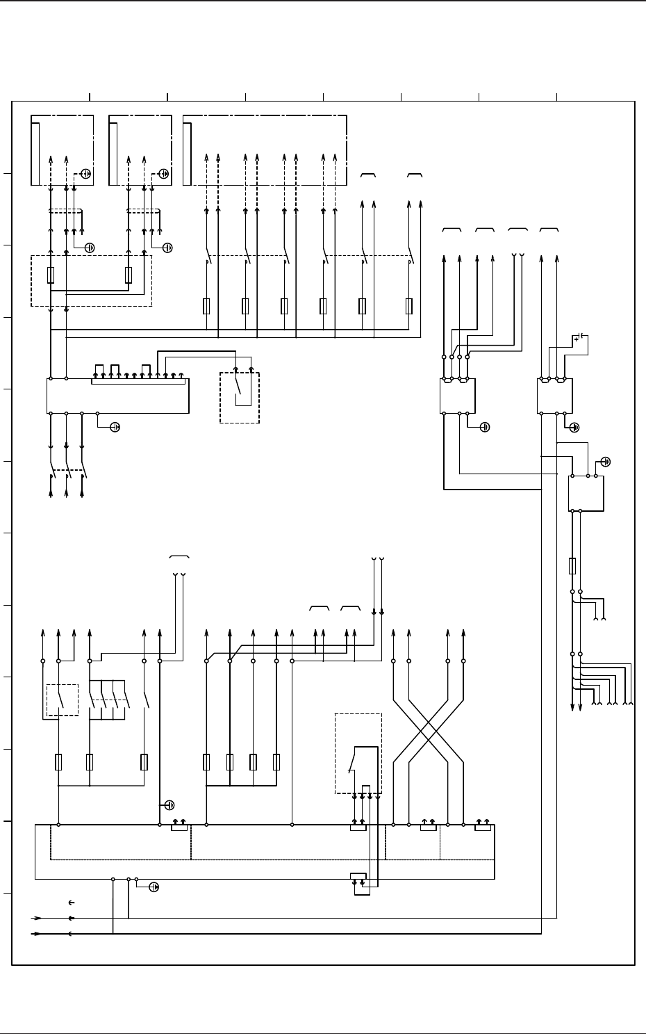
5OM-1610
4-140911-001D(M913WB---0002)
Power Supply Section 2
10D
48D
L120
L220
L1
L2
FG
DC48V
F13
F14
48D3A
48D3B
G2
(10A)
K38
10D
48D3E
F33
48D2E
1 2
U27
DC24V
(L)
(N)
FG
24G
10G
10G
24G
X2711
:2
:1
[B-/01/3H]
[D-/12/1C]
10H
48H
(L)
(N)
FG
DC48V
G7
48H
10H
[R-/01/12D]
DC24V
FG
DC24V
DC24V
(L)
(N)
DC24V
24A2
24F
24C
G1
F7(6.3A)
24A1
24A0
K1A
4 3
F1(3.15A)
13 14
F2(6.3A)
23 24
K25
4 3
F5(6.3A)
F42(5A)
F52(6.3A)
24A
24B
24B3
24B4
K27
F41(3.15A)
24B2
24A3
24B1
24C
24F
10A
10B
10C
10F
48D3F
(10A)
48D3G
F43
48D2G
5 6
48D3H
4 3
[D-/02/2E]
[MH/01/1B,5B]
L110
U27
K1B
33 34
43 44
24A30
CN2CN1
1
3
:1
:2
:3
:4
1
2
CN2
1
2
CN2
1
2
CN2
1
2
X2702
24A1
G
AUX
48D3J
[D-/12/1B]
(5A)
F29
48D3K
(5A)
F30
[D-/22/1B]
U27
3 4
5 6
K10
1 2
3 4
5 6
L240
L140
CN02
11
12
K15
56
X2708
:1
X2708
:2
U27
10D
10D
10D
10D
10D
10D
10D
(10A)
F34
48D2F
3 4
F44
K50
1 2
(10A)
48D2H
48D2J
48D2K
:1
X2712
:2
X2713
24B1
10B
24B1
10B
24A20
L210
L310
[B-/01/3F]
L3
L340
X:G1
:4
:5
:6
X:G1
-1 -2 -3
HWS1800T
CNT
TOG
X15306
[D-/22/1C]
X15506
:A1
X131P1
:A2
:A1
X231P1
:A2
(Robot Cable)
:1
:2
:A1
:A2
:A1
:A2
:A3:A3
:A4
(Robot Cable)
:A3:A3
:A4
10
9
8
7
6
5
4
3
2
1
REF
PV
COM
PC
-S
-V
+S
+V
PF
TOG
(SLOT1,2)
(SLOT3)
(SLOT4)
(SLOT5)
X7201-2
X7201-1
X7201A-2
X7201A-1
:2
:1
X:REED-G04
[LF/01/2D]
F70,71
10A
10B
10F
10C
:2
:1
24A0
24B1
24B2
24B3
24B4
C129
(L)
(N)
FG
DC5V
G8
5J1
10J
:1
:2
:1
:2
:1
:2
:1
:2
(3.15A)
F61
[F-/01/3H]
10J
5J
U27:X2715,X2717
U27:X2716,X2717
Image Distributor
OC Jack
X16504
X:5VOP2
X:5VOP3
X:5VOP4
X:5VOP1
-
+
-
+
RC-
RC+
RC-
RC+
RC-
RC+
+
RC-
RC+
-
+
-
-
+
-
+
-
+
-
+
1
2 3 4 5 6 7 8 9 10 11 12
A
B
C
D
E
F
G
H
*
*
Cooling Fan
[D-/01/1A]
For Safety Circuit
[B-/03/2A]
[B-/03/1A]
[B-/03/1A]
Power Input Circuit
For Safety Circuit
HLS Input Circuit Power Output ON
Option CPU_M
HUB
DC Load Power Source
[BL/02/6E]
Front/Rear Touch Panel Screen
DC Sensor Power Unit
External Power Unit for the Input and Output Machines through I/F
HEAD Unit DC Load Power Source
[BL/01/6F] [BL/03/6F] [C-/*1/8F] [D-/*1/3F]
[F-/01/8F]
[F-/01/9D] [F-/01/9H]
[BM/01/3F]
DC Load Power Source
[BL/04/6F] [F-/07/3F]
[D-/*1/3F]
[D-/02/2E] [F-/02/3F] [F-/13/5F]
-X1300D1
Feeder Bundled Connector Relay
Multi Layer Tray (1)
DC Sensor Power Unit
[D-/12/1E]
-X1300D1
Feeder Bundled Connector Relay
Multi Layer Tray (2)
DC Sensor Power Unit
[D-/22/1E]
HUB Power Connector
for connecting between CPU and M1
X : REED-X19601
[LF/01/2C]
U96:X9601
OP : Coplanarity(IF_PCB)
Contact No. Correction
For Power Unit for the LED Lighting
Control PCB
SL-SRS or DL-SRS
HH-SRS or HM-G500
HH-SRS or HM-G500
Lighting Control PCB Capacitor
OP : Coplanarity (Power to the Sensor)
Rear Side
Front Side
-X1300B2
-X1300B2
External Unit Connecting
Bundled Connector (Rear)
External Unit Connecting
Bundled Connector (Front)
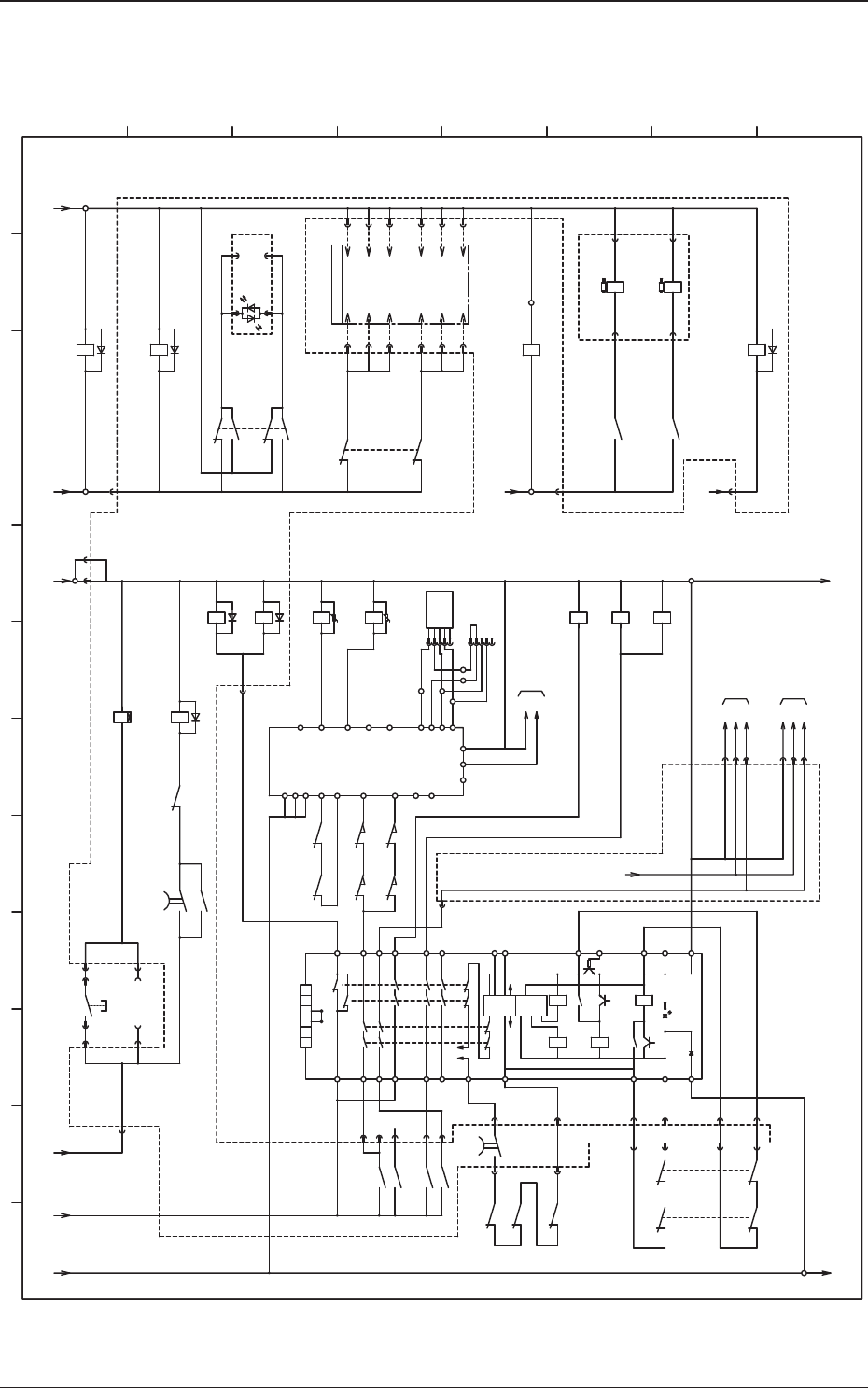
5OM-1610
4-150911-001C(M913WB---0003)
Power Supply Section (Common Relay Circuit)
10A
318
319
K28
A2
A1
-X2742
:9
:9
-X2741
:10
X2742
:10
X2741
X2705
:4
:3
X2704
:4
X2704
:3
34
E2E1
S132
S131
E1 E2
K65A
4 3
K27
121
H101
POWER ON LED
H201
POWER ON LED
RED
GREEN
306
K31
307
3 4
5
8
10 9
X2701
:4
316
K1 K2
K4K3
JP
4
3
b
a
b
a
Control
CircuitTimer
OFF Delay
K4
K3
K2
K1
54
44
34
24
14
A
B
T22
T21
PET11
T12
T31
T32
13
23
33
43
53
A2A1
X2725
:3
X2728
:4
X27150
:3
:5
X27150
X27150
:2
:4
X27150
:6
X27150
-X2704
:2
:2
-X2705 -X2705
:1
:1
-X2704
U27
315
K2
(1sec)
14
13
8
1
K1A
426
421
4 3
K43
420
408
405A
401
S101F
24A1
300
95
K2
441
445
K3
412
K1A
X2701
:1
56
X27150
:7
X2705
[B-/02/5A]
10A
24A1
[B-/02/5B] [B-/03/1H]
2 1
S105F
402
2 1
405
S121B
2 1
409
2 1
412
X2725
:1
X2728
:2
K33B
A1 A2
U
K10
A1 A2
K21
6 8
K38
A1 A2
418
:2
:1
419
22 21
K38
X2723
K66A
24A0
[B-/02/5A]
24A2
[B-/02/5A]
K126
1516
24A3
[B-/02/5B]
K50
A1 A2
K22
6 8
417
22 21
K50
24A2
A2
:2
X2701
:6
X2701
:5
405B
X8203(1CH)
K129
3 4
390
:2
X2762
:4
X2762
:6
X2762
10 9
393
:2
X2763
:4
X2763
:6
X2763
:1
X2762
:3
X2762
:5
X2762
:1
X2763
:3
X2763
:5
X2763
[F-/12/5D]
A1
A2
K1B
[B-/02/5A]
24A1
[B-/03/9A]
10A
[B-/03/12A]
[B-/03/7H]
K33A
A1 A2
U
K11
6 8
34
K15
21 22
K10
1 2 3 4 5 6
1
K31
12
1
K31B
12
6261
U27
:12
X27150
:11
X27150
:10
X27150
:9
X27150
:8
X27150
:1
X27150
:13
X27150
336
334
331
332
333
335
24A2
:1
X27153
:2
:3
:1
X27154
:2
:3
24A2
610
K2
14 13
X1
X2
:B1
:B2
:B3
:B1
:B2
:B3
[D-/12/2E]
-X1300D1
[D-/22/2E]
-X1300D1
S105FS121B
-X2701
:3
T32
Y1
A1
441A
S131 S132
444
S131 S132
T33
T31
415
K33B
416
2221
K33A
T22
T12
T42
T41
S14
S24
2221
1112 1112
3132 3132
D1
D2
D3
D4
W
BK
BR
BL
K4
440
443
A2X1X2
S44
S54
L1
D1
D3
D4
D2 D
10A24A1
24A1
430
429
414
:47
:22
10A
446
S151F
Y
:3
X:S151F
:2
:4
:1
:5
:3
X:S151B
:2
:4
:1
:5
1
2 3 4 5 6 7 8 9 10 11 12
A
B
C
D
E
F
G
H
POWER ON PB (Front)
Control Panel (Front)
Emergency Stop
Main Power Input Delay
Power Supply for Control
Head Main Power Input
Conveyor Main Power Input
CUT(1)(2) Main Power Input
Motion Control PCB :U82
DI Connector 1CH
Power ON (Green) Light ON
Safety Relay Monitor
External Unit Connecting Bundled
Connector (Rear)
External Unit Connecting Bundled
Connector (Front)
Linear Motor Main Power Input
Linear Motor Main Power Input
Feeder Cart
Detection (Front)
Sensor Circuit Correction
HLS Input Power Input
Cover Lock (Rear Side)
Cover Lock (Front Side)
DC Load Power Input
Conveyor Emergency Stop
To Transfer Unit Motor
Driver Conveyor Emergency
Stop Input
SL-SRS or DL-SRS
PC Power Input
Emergency Stop
Rear Center
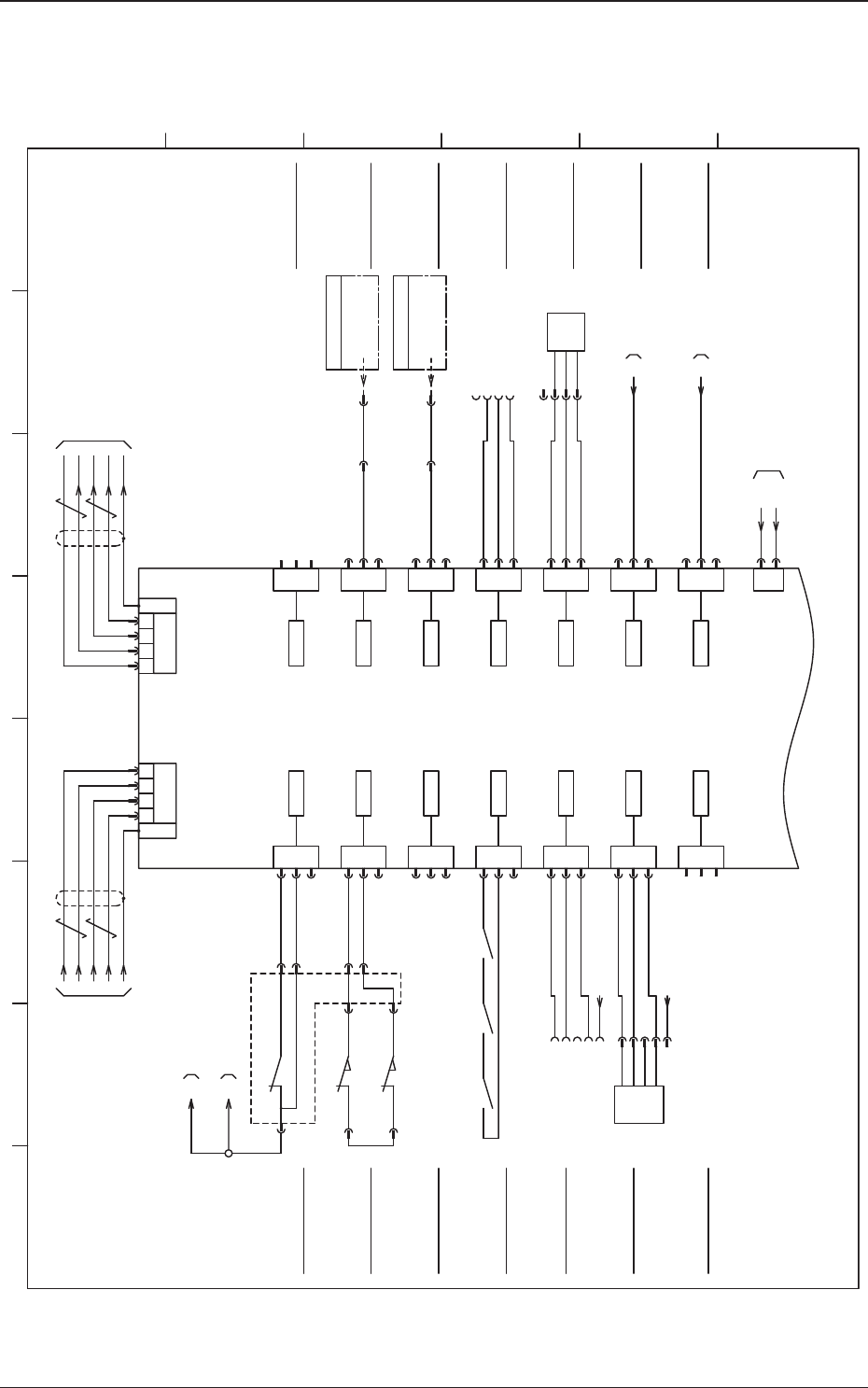
5OM-1610
4-160911-001C(M913WBL--0001)
U05 I/O PCB STLT ILB 1/2
3
2
1
3
2
1
3
2
1
3
2
1
3
2
1
XCN10
3
2
1
3
2
1
3
2
1
3
2
1
3
2
1
XCN17
XCN11 XCN18
XCN12 XCN19
XCN13 XCN20
XCN14
XCN15
9 7 5 753 93
TX+
TX-
RX+
RX-
XCN1 XCN2
3
2
1
XCN16
3
2
1
XCN21
3
2
1
XCN22
3
2
1
XCN23
GND(B)
24V(B)
GND(B)
24V(B)
Shielded Shielded
500
:B1
X2761
:A1
X0511
10B
:2
:3
:1
504
24B1
10B
505
24B1
508
:C6
509
501
S131
51 52
:B2
:8
X2742
:8
X2741
:7
X2741
:7
X2742
S132
52 51
:A2
X2761
513
X0510
X0514
X0515
X0516
X0518
X0519
X0520
X0523
EMR
SF CVR RL
S FLOAT R
S FLOAT F
CK MS R
CK MS F
HD INLK1
HD INLK2
:3
:5
:7
:9
:9
:7
:5
:3
[BL/03/3A]
3
XCN3
X0503
4
10B
24B1
[B-/02/5C]
GND(B)
24V(B)
GND(B)
24V(B)
GND(B)
24V(B)
GND(B)
24V(B)
GND(B)
24V(B)
GND(B)
24V(B)
GND(B)
24V(B)
GND(B)
24V(B)
GND(B)
24V(B)
GND(B)
24V(B)
GND(B)
24V(B)
GND(B)
24V(B)
10B
10B
U27
X0501
X0502
3 4
K31B
K33B
4344
TX+
TX-
RX+
RX-
X2723
:3
500
-X1300F3
[D-/12/6E]
:1
[D-/22/6E]
:1
[F-/13/5A]
501A
512
X0522
X0512
X0513
RSV IN1
XY POFF
K33A
4443
Q201
503A503B 10B
510
511
X0521
503
FB INLK1
FB INLK2
F FLOAT R
F FLOAT F
:2
-X12501-X22507
:C6:2
-X12501-X22507
(Robot Cable)
(Robot Cable)
-X1300F3
HEAD STP
HEAD STP
:2
[D-/12/6E]
-X1300F3
:2
[D-/22/6E]
-X1300F3
:3
:4
:1
:2
B0521
+
-
BL
BR
BK
OUT1
:3
:4
:1
:2
XB0521
XB0520
XB0514
B0515
XB0515
:4
:5
[D-/21/7E]
U06-X0644
BK
O
:2
:3
:1
-
BL
OUT1
BR
+
OUT2
:4
:5
U06-X0645
N.C
N.C
[D-/21/7F]
OP
U12 (STLT PWR)
X1201(CN1)
ch1-1
U85 HLSC
CH1-CN1
ch1-1
OP
OP
1 2 3 4 5 6 7 8
A
B
C
D
E
F
Emergency Stop
Safety Monitor
Pickup Error Component
Detection (Rear)
Pickup Error Component
Detection (Front)
Feeder Open Area Sensor
Detection (1)
OP
Cover Lock Check
Connector Case
CB Error (Beam General)
External Unit Connecting Bundled Connector (Rear)
Back Up
Beam Main Power Detection
External Unit Connecting Bundled Connector (Front)
(Rear)
(Front)
Case FG
I/O P.C.B
STLT_ILB
U05
Case FG
Connector Case
Feeder Open Area Sensor
Detection (2)
Head Interlock (M1)
Head Interlock (M2)
Power for Input
Feeder Disengaged Latch
Detection (Rear)
Feeder Disengaged Latch
Detection (Front)
Feeder Base Interlock (Rear)
Rear Side
Front Side
Feeder Base Interlock (Front)
External Unit Connecting Bundled Connector (Rear)
External Unit Connecting Bundled Connector (Front)
HH-SRS or HM-G500
HH-SRS or HM-G500