5OM-1626-001_w.pdf - 第159页
5OM-1610 4-44 091 1-001-(M920WCU--0001) Cutter Motor Circuit Diagram SSG M 4 2 1 5 3 CN2 X6302 CAN H(+) CAN L(-) GND DC24V GND(SD) 1 2 CN1 X6301 3 2 5 1 4 W V (BK) U FG CN3 X6303 6 (BK) M63 CT -Axis A2 B1 A3 A1 B2 S1 S4 …
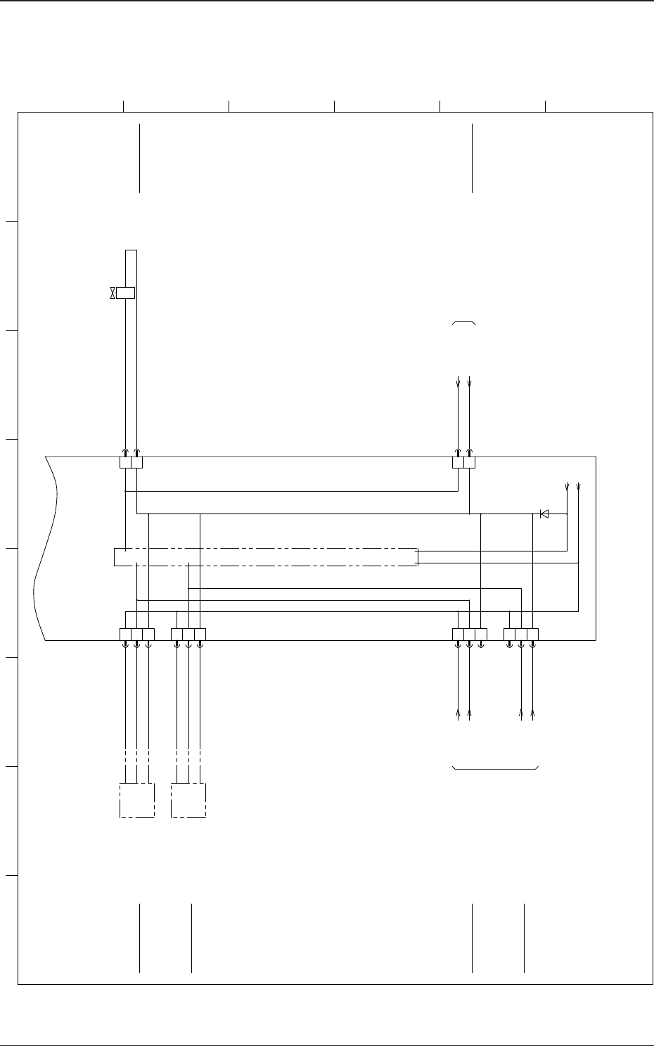
5OM-1610
4-430911-001-(M920WFB--0002)
Feeder Base Circuit Diagram 2
Y6908
-
OUT
+
BR
BK
BL
B6904
X6913
1
2
CN13
X6914
CN14
1
2
3
3
2
1
CN10
X6910
X6912
CN12
1
2
3
X6915
CN15
1
2
3
CN11
2
1
X6911
10B1
24VB1
24VBO
24VBO
24VBO
24VBO
24VBO
24VB1
Internal I/O Circuit
B6906
BL
BK
BR
+
OUT
-
+24V
GND
+24V
X300E
:8
:9
:10
:11
X300E
:7
:6
[FB/01/2D]
[FB/11/2D]
U69
I/O P.C.B
STLT_FB
Extermal Command
(Feeder Clamping)
for Offline Control
Feeder Clamp
(Clamping)
(Unclamping)
Feeder Clamp Lower Limit
Outside Notification (Clamping)
for Offline Control
Feeder Clamp Upper Limit
Outside Notification (Unclamping)
for Offline Control
Feeder Clamp Upper Limit
Feeder Clamp Lower Limit
Feeder Base Offline Control
External Unit Connecting Bundled Connector
To X300E
1 2 3 4 5 6 7 8
A
B
C
D
E
F
Feeder Base Offline Control
External Unit Connecting Bundled Connector
To X300E
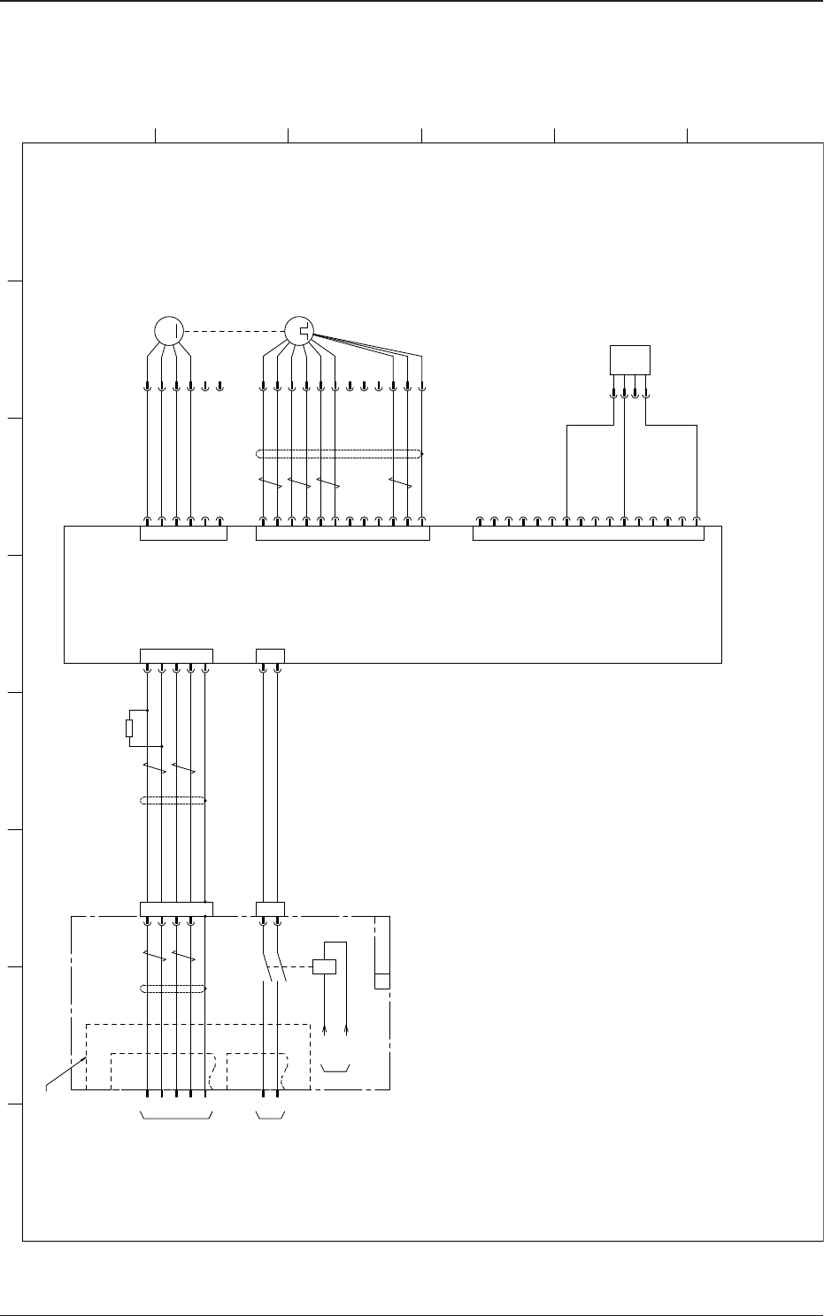
5OM-1610
4-440911-001-(M920WCU--0001)
Cutter Motor Circuit Diagram
SSG
M
4
2
1
5
3
CN2
X6302
CAN H(+)
CAN L(-)
GND
DC24V
GND(SD)
1
2
CN1
X6301
3
2
5
1
4
W
V
(BK)
U
FG
CN3
X6303
6
(BK)
M63
CT-Axis
A2
B1
A3
A1
B2
S1
S4
R1
S2
S3
CN5
X6305
B3
R2
A6
B5
VCC
GND
B6
GND(SD)
M63
:1
:2
:3
:4
M63P
:A1
:B1
:A2
:B2
:A3
:B3
3
2
5
1
4
AIN
F-PLS+
GND(COM-)
R-PLS-
CN7
X6307
6
F-PLS-
8
7
AUX
GND
9
C-RST
10
12
11
F-LMT
R-LMT
13
SV-ON
15
14
ALM
INT
16
+24V(COM+)
R-PLS+
ALM-RST
A63
Servo Motor AMP
[D-/12/4B]:(1)
:3
X300E
:4
:1
:2
:5
:5
:6
3
X16302
6
1
5
SD
GND
DC48V
(SV-NET)
(POWER)
(MOTOR)
(SENSOR)
(I/O)
:5
:6
A5
B4
A4
NC
NC
NC
:A4
:B4
:A5
:B5
:A6
:B6
OUT1
OUT2
BK
WH
-
BL
+
BR
B6302
SV-NET
[D-/12/8A]:(1)
GND
DC48V
DC48V
R63
120Ω
X16301
1
2
B module
(6Pins)
X300B
[D-/22/8A]:(2)
[D-/22/4B]:(2)
14 13
24 23
A2 A1
K52
24G2
10G
[FB/01/3G]
FB-SRS
U
E module
(12Pins)
Origin (-)
Main Circuit
Power Supply
Terminal Resistance
EMI Case
External Unit Connecting
Bundled Connector
X30
1 2 3 4 5 6 7 8
A
B
C
D
E
F
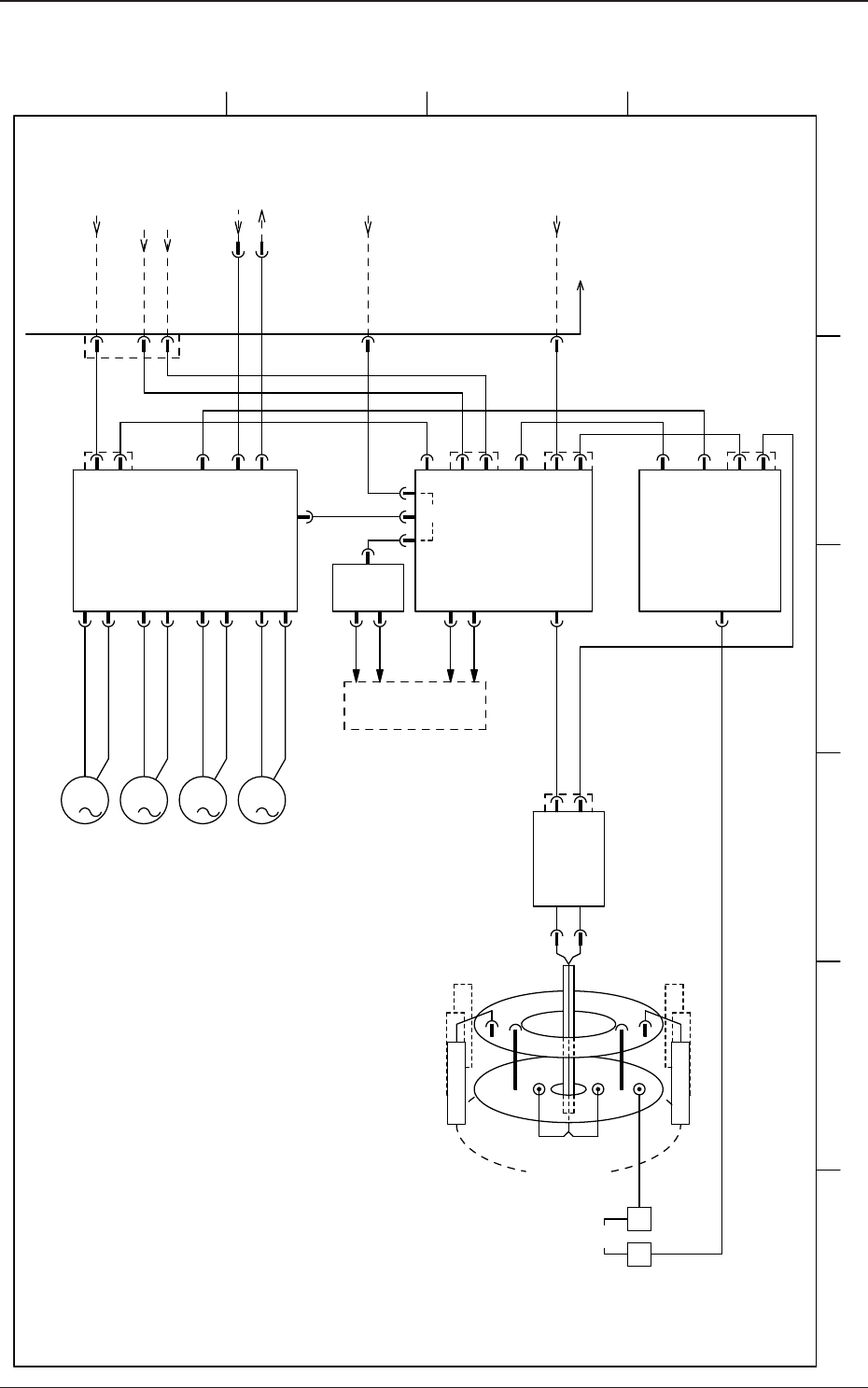
5OM-1610
4-450911-001-(M916WA---0001)
High-Speed Head Block Diagram
3
M
3
M
3
M
3
M
HLS HLS
HLSPWR
24B124F
24F
DC48V
SSCNET
(B1) (F)
DC24V
HLS
A31
Servo Motor AMP
U25
I/O PCB
U03
Line Sensor AMP
STLT HD2
U37
Slip Rings
U147
Connector
PCB
M31
DD
M32
NS
M33
HL
M34
NL
I/O
I/O
U04
I/O PCB
(STLT HD)
PWR
PWR HLS
PWR
24F24B1
SSCNET
24V48V
Robot Cable
PWR
X131P1 X12501 X22501
X1311A X1311B
Main Boby Side
SENSOR HEAD
T
R
PWR HLS
Pulse
Head Section
Load and Sensor
Vacuum Switchover Valve 1
15 Nozzle Head
Vacuum Switchover Valve 15
1 2 3 4
A
B
C
D
E
F