5OM-1626-001_w.pdf - 第55页
5OM-1610 1-2 Pneumatic and Mounting Diagrams 13 1 1 12 12 13 13 1 1 1 1 2 1 12 12 22 2-7 2-1 2-6 2 1 1 2-2 2-3 2-4 1 1 19 16 16 20 17 15 7 6 1 19 19 19 Nozzle Stocker (1) Positioning (2) Feeder Base (2) Cart Collective C…
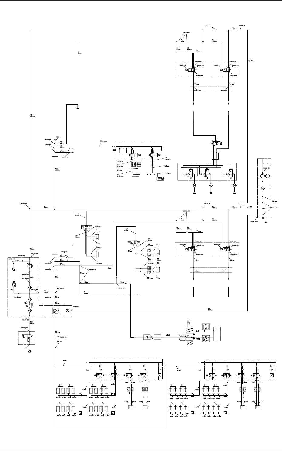
5OM-1610
1-1
Pneumatic and Mounting Diagrams
0911-001
Entire System (Pneumatic Diagram)
Feeder Clamp 2 Open / Close
Positioning U/D (2)
Positioning Unit
Lowering Prevention (2)
Multi Layer Tray Feeder (2)
Beam Relay Panel
Right Side
Cylinder
Left Side Cylinder
Stocker 1 U/D
Shutter 1 Open / Close
Head (1)
Nozzle1 Nozzle2 Nozzle15
Stocker 2 U/D
Shutter 2 Open / Close
Head (2) Head (2)
Beam Relay Panel
Right Side
Cylinder
Left Side
Cylinder
Exhaust
Setup
0.05MPa
Setup
0.35MPa
Setup
0.45MPa
Setup
0.4MPa
PCB Stopper AL
Dual Transfer Conveyor
robot Cable robot Cable
robot Cable robot Cable
Movable Chute 1Z Clamp R
Movable Chute 3Z Clamp R
Movable Chute 2Z Clamp R
Fixed Chute Z Clamp R
PCB Stopper BL
PCB Stopper AR PCB Stopper BR
Movable Chute 1Z Clamp L
Movable Chute 3Z Clamp L
Movable Chute 2Z Clamp L
Fixed Chute Z Clamp L
Hose Nipple
5OM-1610
1-2
Pneumatic and Mounting Diagrams
13
1 1
12
12
13
13
1 1
1 1
2 1
12
12
22
2-7
2-1
2-6
2
1 1
2-2
2-3
2-4
1 1
19
16
16
20
17
15
7
6
1
19
19
19
Nozzle Stocker (1)
Positioning (2)
Feeder Base (2)
Cart Collective Connector
Multi Layer Tray Feeder (2)
Transfer
(PCB Z Clamp and PCB Stopper)
Setup
0.05MPa
Hose NippleY
Positioning (2)
Setup
0.35MPa
Setup
0.45MPa
Setup
0.4MPa
Nozzle Stocker (2)
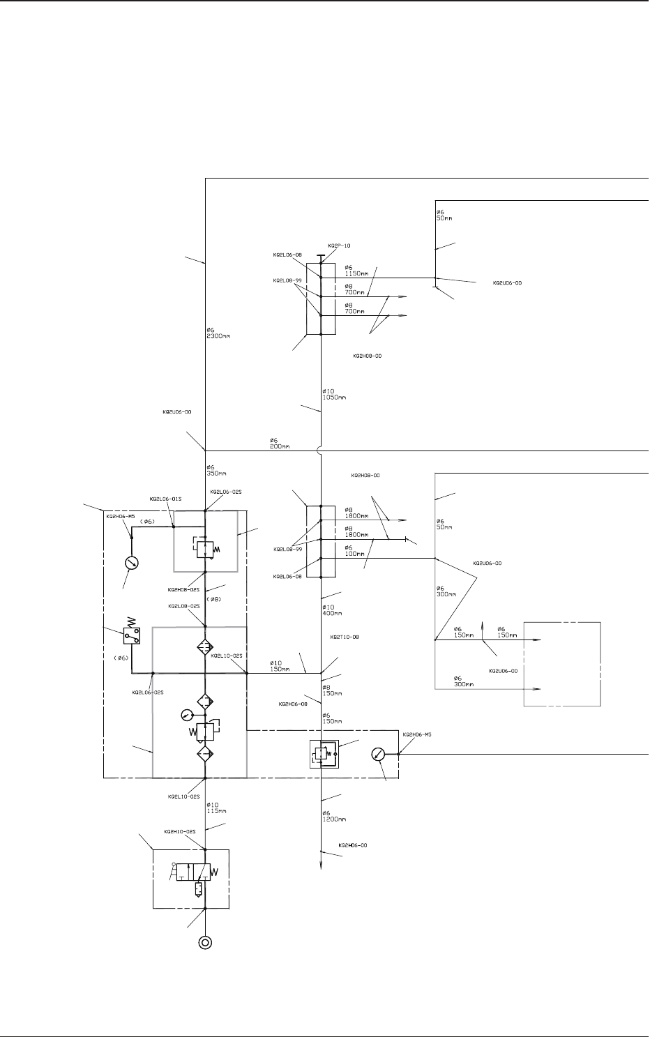
0911-001-(1091301500)
Main Body (Pneumatic Diagram)
5OM-1610
1-3
Pneumatic and Mounting Diagrams
19 19
18
19 19
18
Beam Relay Panel
Head (1)
Head (1)
Y0938 Air/Vacuum Head Change-Over Valve
Y0939 High-Speed/Multi-Functional Head
Change-Over Valve
Specification 8
Specification 9
Beam Relay Panel
Specification 9
Head (2)
Head (2)
Y0638 Air/Vacuum Head Change-Over Valve
Y0639 High-Speed/Multi-Functional Head
Change-Over Valve
Specification 7
(Blue)
(Blue)
(Blue)
Exhaust
Specification 6
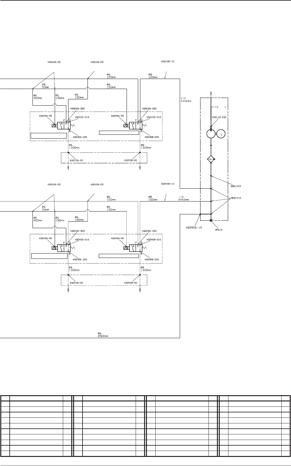
0911-001-(1091301500)
Main Body (Pneumatic Diagram)
No. Name Q’ty No. Name Q’ty No. Name Q’ty No. Name Q’ty
1 Air Supply Unit 1 5 Solenoid Valve Unit 1 18 Different Straight 2
2 Air Supply Unit 1 6 Manifold Unit 1 19 Union Y 11
2-1 Vacuum Gauge 1 7 Manifold Unit 1 20 Different Cheese 1
2-2 Combination Unit 1 11 Tube
φ
6 1 21 Plug 1
2-3 Pressure Switch 1 12 Tube
φ
8 1 22 Plug 1
2-4 Pressure Gauge 1 13 Tube
φ
10 1
2-6 Regulator 1 14 Tube
φ
10BU 1
2-7 Regulator 1 15 Straight 1
3 Vacuum Pump Unit 1 16 Straight 4
4 Solenoid Valve Unit 1 17 Different Straight 1