5OM-1626-001_w.pdf - 第57页
5OM-1610 1-4 Pneumatic and Mounting Diagrams 091 1-001-(1091401200) Main Body (Mounting Diagram) 1-4 1-1 1-3 1-2 2-3 2-10 2-7 2-6 2-12 2-7 2-9 2-1 2-4 2-13 2-14 2-14 2-2 2-12 3-6 3-5 3-4 3-1 3-1 3-8 3-7 3 1 2 No. Name Q’…
5OM-1610
1-3
Pneumatic and Mounting Diagrams
19 19
18
19 19
18
Beam Relay Panel
Head (1)
Head (1)
Y0938 Air/Vacuum Head Change-Over Valve
Y0939 High-Speed/Multi-Functional Head
Change-Over Valve
Specification 8
Specification 9
Beam Relay Panel
Specification 9
Head (2)
Head (2)
Y0638 Air/Vacuum Head Change-Over Valve
Y0639 High-Speed/Multi-Functional Head
Change-Over Valve
Specification 7
(Blue)
(Blue)
(Blue)
Exhaust
Specification 6
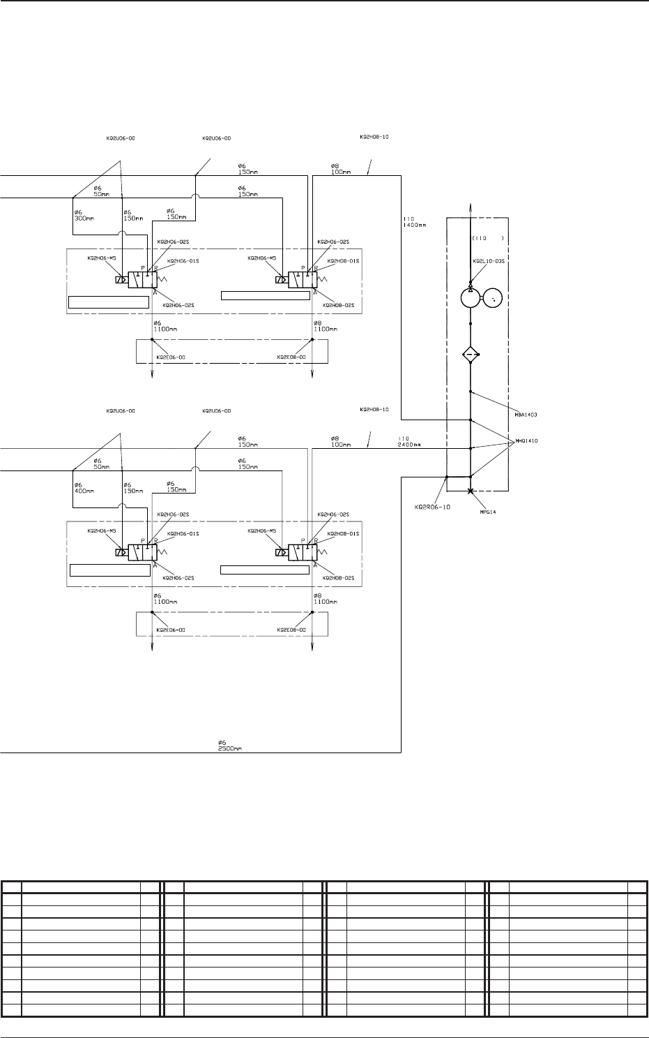
0911-001-(1091301500)
Main Body (Pneumatic Diagram)
No. Name Q’ty No. Name Q’ty No. Name Q’ty No. Name Q’ty
1 Air Supply Unit 1 5 Solenoid Valve Unit 1 18 Different Straight 2
2 Air Supply Unit 1 6 Manifold Unit 1 19 Union Y 11
2-1 Vacuum Gauge 1 7 Manifold Unit 1 20 Different Cheese 1
2-2 Combination Unit 1 11 Tube
φ
6 1 21 Plug 1
2-3 Pressure Switch 1 12 Tube
φ
8 1 22 Plug 1
2-4 Pressure Gauge 1 13 Tube
φ
10 1
2-6 Regulator 1 14 Tube
φ
10BU 1
2-7 Regulator 1 15 Straight 1
3 Vacuum Pump Unit 1 16 Straight 4
4 Solenoid Valve Unit 1 17 Different Straight 1
5OM-1610
1-4
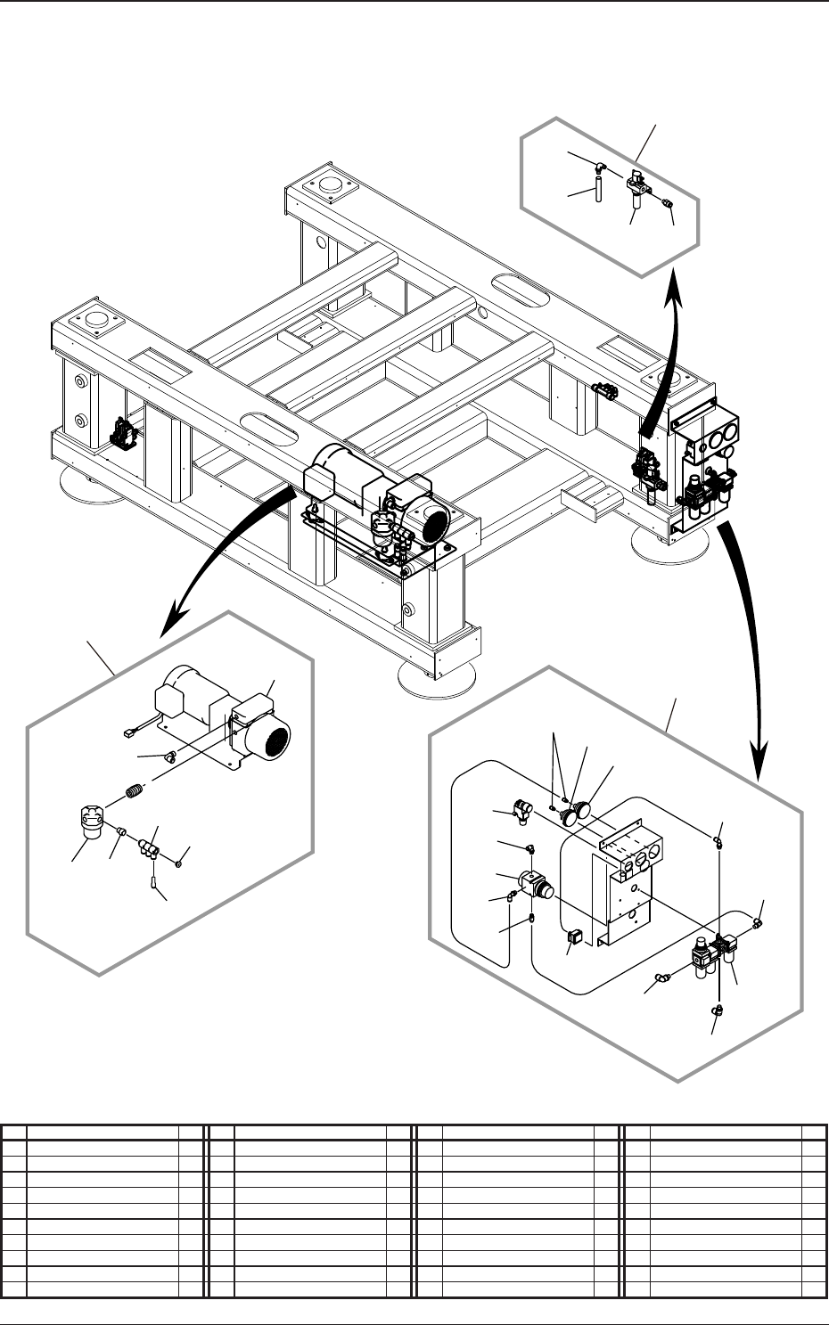
Pneumatic and Mounting Diagrams
0911-001-(1091401200)
Main Body (Mounting Diagram)
1-4
1-1
1-3
1-2
2-3
2-10
2-7
2-6
2-12
2-7
2-9
2-1
2-4
2-13
2-14
2-14
2-2
2-12
3-6
3-5
3-4
3-1
3-1
3-8
3-7
3
1
2
No. Name Q’ty No. Name Q’ty No. Name Q’ty No. Name Q’ty
1 Air Supply Unit 1 2-6 Regulator 1 3-4 Bush 1
1-1 Combination Unit 1 2-7 Regulator 1 3-5 Universal Quick 3
1-2 Female/Male Elbow 1 2-9 Half Union 2 3-6 Plug 1
1-3 Single-Ended Hose Nipple 1
2-10
Half Union 1 3-7 Elbow Union 1
1-4 Half Union 1
2-11
Elbow Union 1 3-8 Reducer 1
2 Air Supply Unit 1
2-12
Elbow Union 2
2-1 Vacuum Gauge 1
2-13
Elbow Union 1
2-2 Combination Unit 1
2-14
Elbow Union 2
2-3 Pressure Switch 1 3 Vacuum Pump Unit 1
2-4 Pressure Gauge 1 3-1 Vacuum Pump 1
5OM-1610
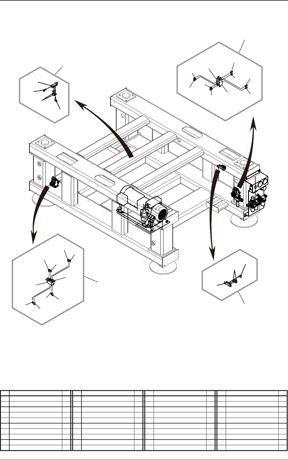
1-5
Pneumatic and Mounting Diagrams
0911-001-(1091401200)
Main Body (Mounting Diagram)
5-1
5-1
5-5
5-3
5-5
5-5
5-6
5-3
5-7
5-4
4-3
4-7
4-1
4-1
4-3
4-5
4-4
4-6
4-5
4-5
7-3
7-1
7-4
7-2
6-3
6-1
6-2
4
5
6
7
No. Name Q’ty No. Name Q’ty No. Name Q’ty No. Name Q’ty
4 Solenoid Valve Unit 1 5-4 Half Union 1 7-2 Straight Elbow 2
4-1 Solenoid Valve 2 5-5 Half Union 3 7-3 Reducer Elbow 1
4-3 Half Union 2 5-6 Half Union 1 7-4 Plug 1
4-4 Half Union 1 5-7 Half Union 1
4-5 Half Union 3 6 Manifold Unit 1
4-6 Half Union 1 6-1 Manifold 1
4-7 Half Union 1 6-2 Straight Elbow 2
5 Solenoid Valve Unit 1 6-3 Reducer Elbow 1
5-1 Solenoid Valve 2 7 Manifold Unit 1
5-3 Half Union 2 7-1 Manifold 1