5OM-1626-001_w.pdf - 第62页
5OM-1610 1-9 Pneumatic and Mounting Diagrams 091 1-001-(309160320C) High Speed Head Unit (Pneumatic Diagram) 1 3 2 4 6 5 From Main Body Robot Cable Nozzle1 Nozzle2 Nozzle3 No. Name Q’ty No. Name Q’ty No. Name Q’ty No. Na…
5OM-1610
1-8
Pneumatic and Mounting Diagrams
0911-001-(2091702300)
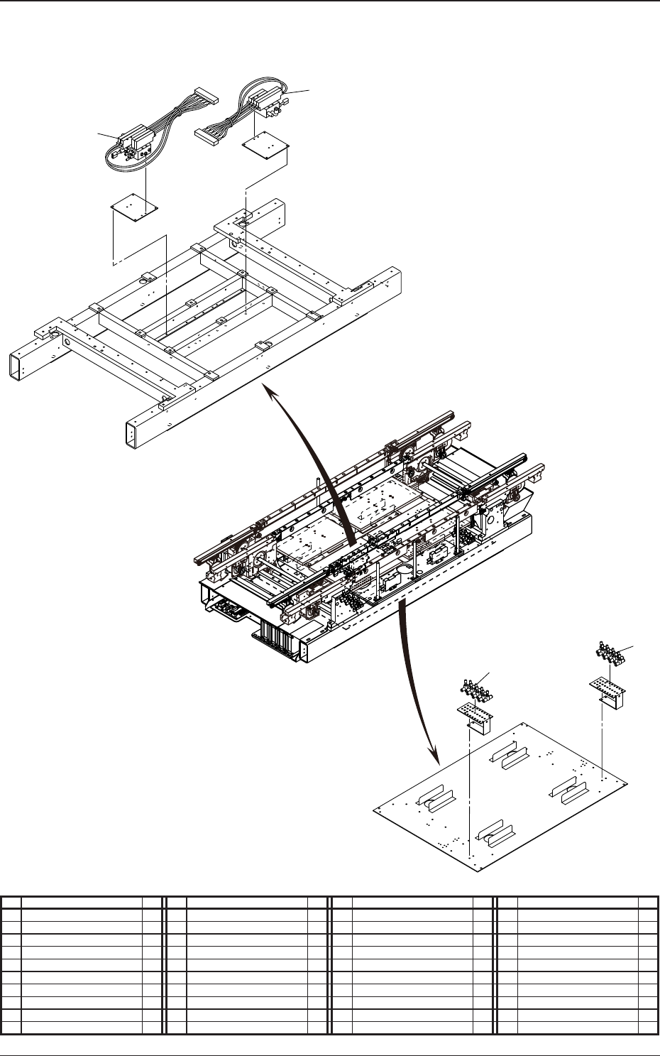
Conveyor (Mounting Diagram)
5
6
12
11
No. Name Q’ty No. Name Q’ty No. Name Q’ty No. Name Q’ty
5 Solenoid Valve 1
6 Solenoid Valve 1
11 Speed Controller 8
12 Speed Controller 8
5OM-1610
1-9
Pneumatic and Mounting Diagrams
0911-001-(309160320C)
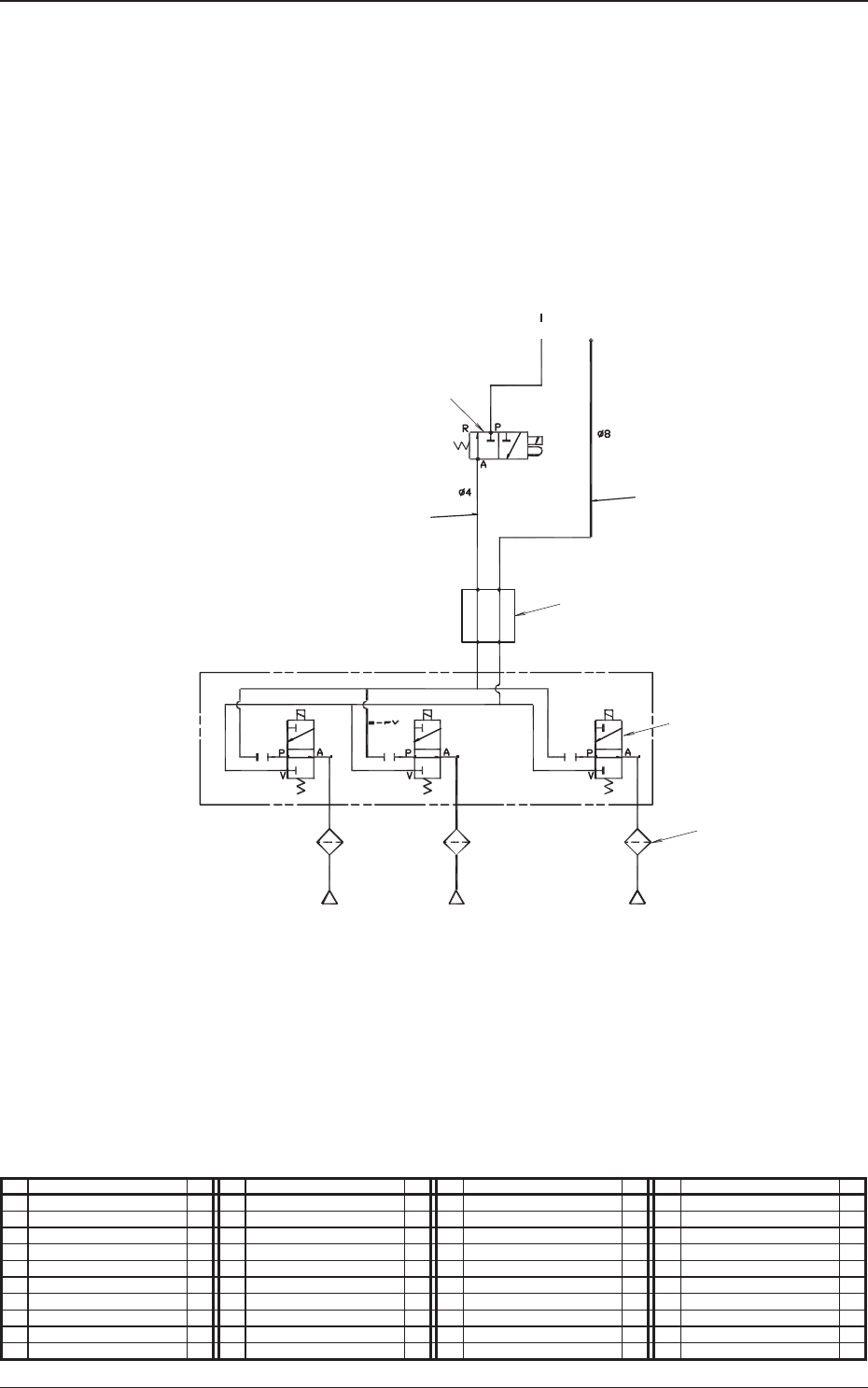
High Speed Head Unit (Pneumatic Diagram)
1
3
2
4
6
5
From Main Body
Robot Cable
Nozzle1 Nozzle2 Nozzle3
No. Name Q’ty No. Name Q’ty No. Name Q’ty No. Name Q’ty
1 Tube
φ
4 1
2 Tube
φ
8 1
3 Solenoid Valve 1
4 Rotary Joint 1
5 Solenoid Valve 15
6 Filter 15
5OM-1610
1-10
Pneumatic and Mounting Diagrams
0911-001-(309160320C)
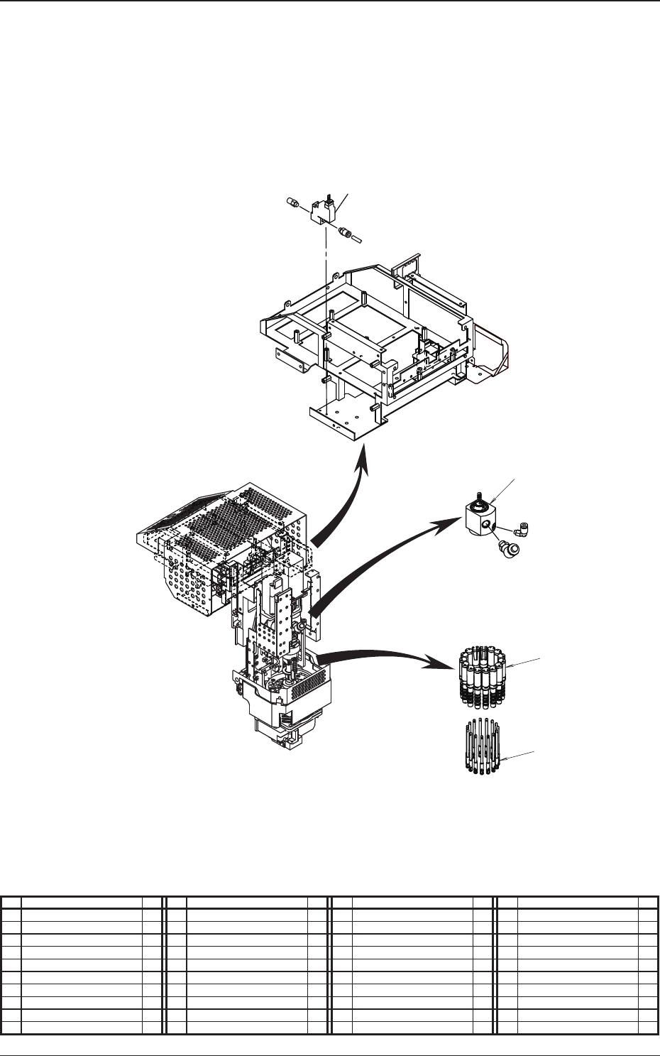
High Speed Head Unit (Mounting Diagram)
3
5
4
6
No. Name Q’ty No. Name Q’ty No. Name Q’ty No. Name Q’ty
1 Solenoid Valve 1
2 Rotary Joint 1
3 Solenoid Valve 15
4 Filter 15