YSI_Prog_E - 第100页
2-29 2 Creating inspection pr ograms 2.6 View settings A "view" is the camera field-of-view used b y the the inspection machine to inspect a board. In the view settings, views are set for locations on the board…
2-28
2
Creating inspection programs
7
Press the [Light List] button and select a clear image.
By pressing the [Light List] button, a list of images appears. Select an image in which the mark appears
clearly from the image list, and press the [Set] button. When setting is complete, the display returns to
the "Bad Mark" screen, and the "D. Light Type" is set.
8
Press the [Thresh] button and set the threshold value.
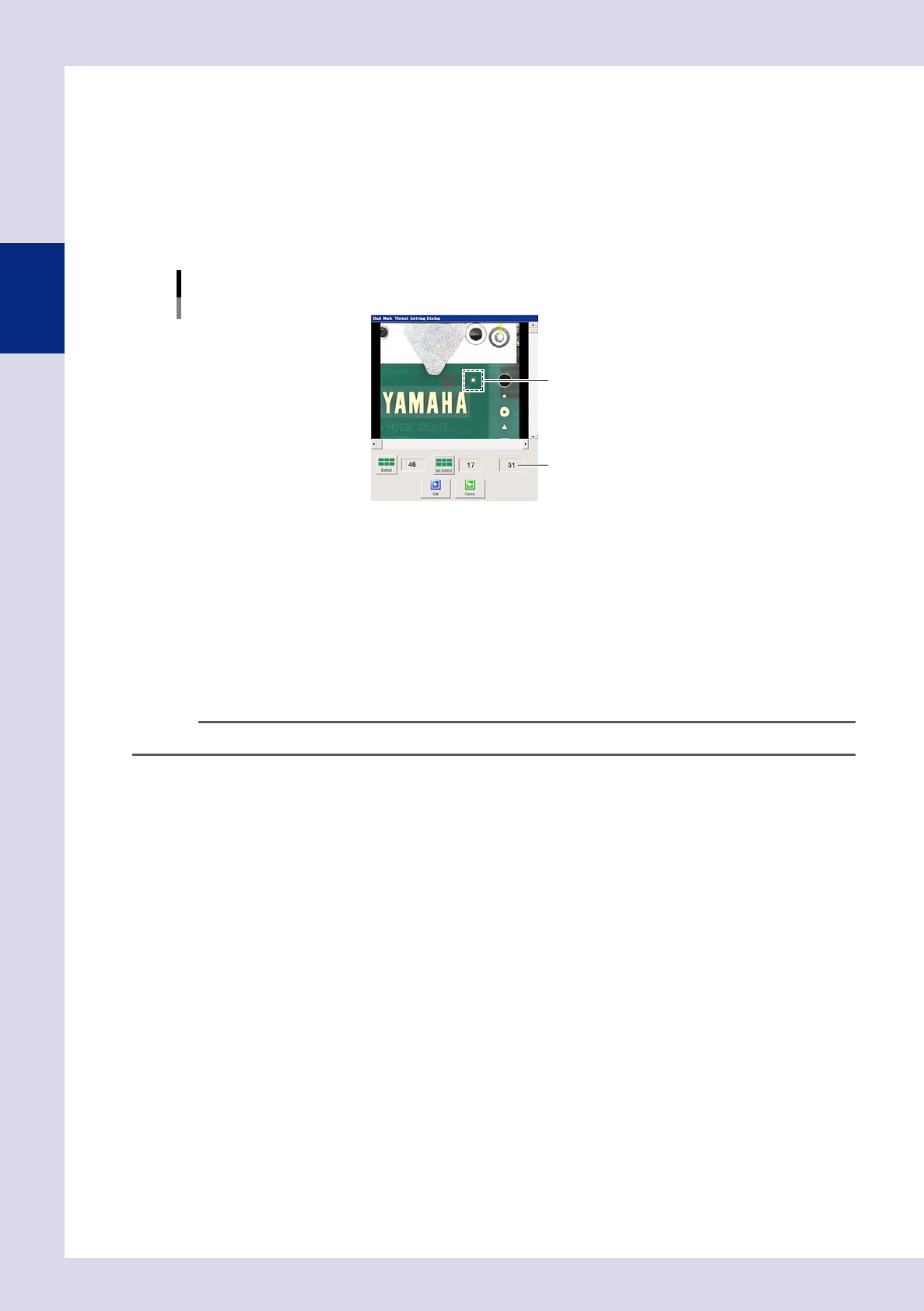
By pressing the [Thresh] button, a "Bad mark threshold value setting" screen appears. Set the threshold
value using the following procedure.
1. Click the bad mark on the screen, and move the camera axis until the mark enters the red box.
"Bad mark threshold value setting" screen
Threshold value
Select the bad mark.
24226-P6-00
2. Press the [Detect] button to display the luminance when a bad mark exists.
3. Click a position with no bad mark, and move the camera axis to a position with no marks.
4. Press the [No Detect] button to display the luminance when no bad mark exists.
5. The intermediate value is set as the threshold value. Press the [Set] button to set the value for "J.
Thresh". By pressing the [Close] button without pressing the [Set] button, the acquired threshold value
is not set.
9
Perform a test.
Press the [Test] button to verify whether the mark is judged correctly.
TIP
The mark recognition coordinates appear in the upper left of the mark screen.
0
Press the [Save] button to save the inspection program.
2-29
2
Creating inspection programs
2.6 View settings
A "view" is the camera field-of-view used by the the inspection machine to inspect a board. In the view
settings, views are set for locations on the board to be inspected, and the board images for each view are
saved. When performing automatic inspection, the inspection head moves to the set coordinates to perform
inspection. View settings cannot be specified with the optional iPro offline software.
TIP
With the optional iPro ofine software, saved images are used to make changes to data. Furthermore, saved images
are also displayed in the Repair Station (option) OK images.
2.6.1 Saving view images
Capture all view images for the board set on the inspection machine, and save a standard image.
1
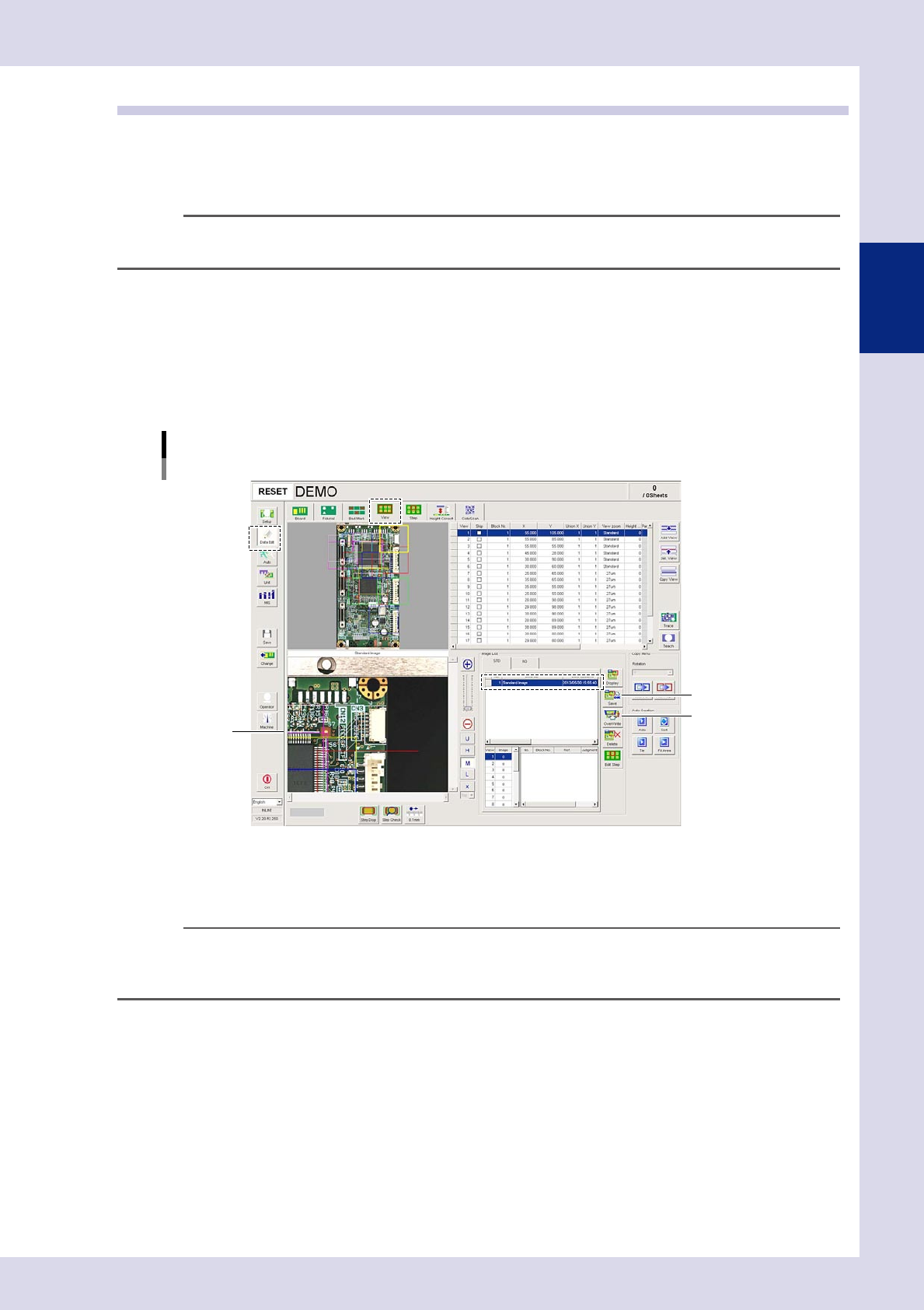
Press the [Data Edit] button and open the "View" tab.
2
Save the view image.
Press the image list [Save] button. The view registered first is saved as the standard image.
[Data Edit] – [View] screen
Saving the standard image
[Save] button
[OverWrite] button
View image
24227-P6-00
3
Save the inspection programs.
Press the [Save] button in the button area to save the board program.
n
NOTE
• If editing the view after saving the standard image, select the standard image from the OK image list, and then
press the image list [OverWrite] button.
• The saved image can be displayed by pressing the [List] button in the [Data Edit] - [Step] screen.
n
Saving additional OK images
If saving multiple OK images, after saving the standard image, replace the board and press the image list [Save] button.
The images are saved with the board ID for the saved date. To display saved images, press the [List] button in the "Step"
tab, open the "Image List" screen, select a board ID, and then press the [OK] button.
2-30
2
Creating inspection programs
n
Saving NG images
View images for which NGs occurred during automatic inspection are automatically saved. By pressing the "NG Image"
tab, a list of saved data appears. To display saved images, press the [List] button in the "Step" tab, open the "Image List"
screen, select a board ID, and then press the [OK] button.
Setting method
Press the [Machine] button to open a settings screen, select "Machine Information"
→
"Installation Setting", and select
"NG Image" from the "Image Setting" - "Image Auto SAVE" drop-down list.
c
When saving NG images, only those view images for which an NG has occurred are saved.
2.6.2 Using view images
Display a saved view image, and check the created inspection program or make changes to parameters.
1
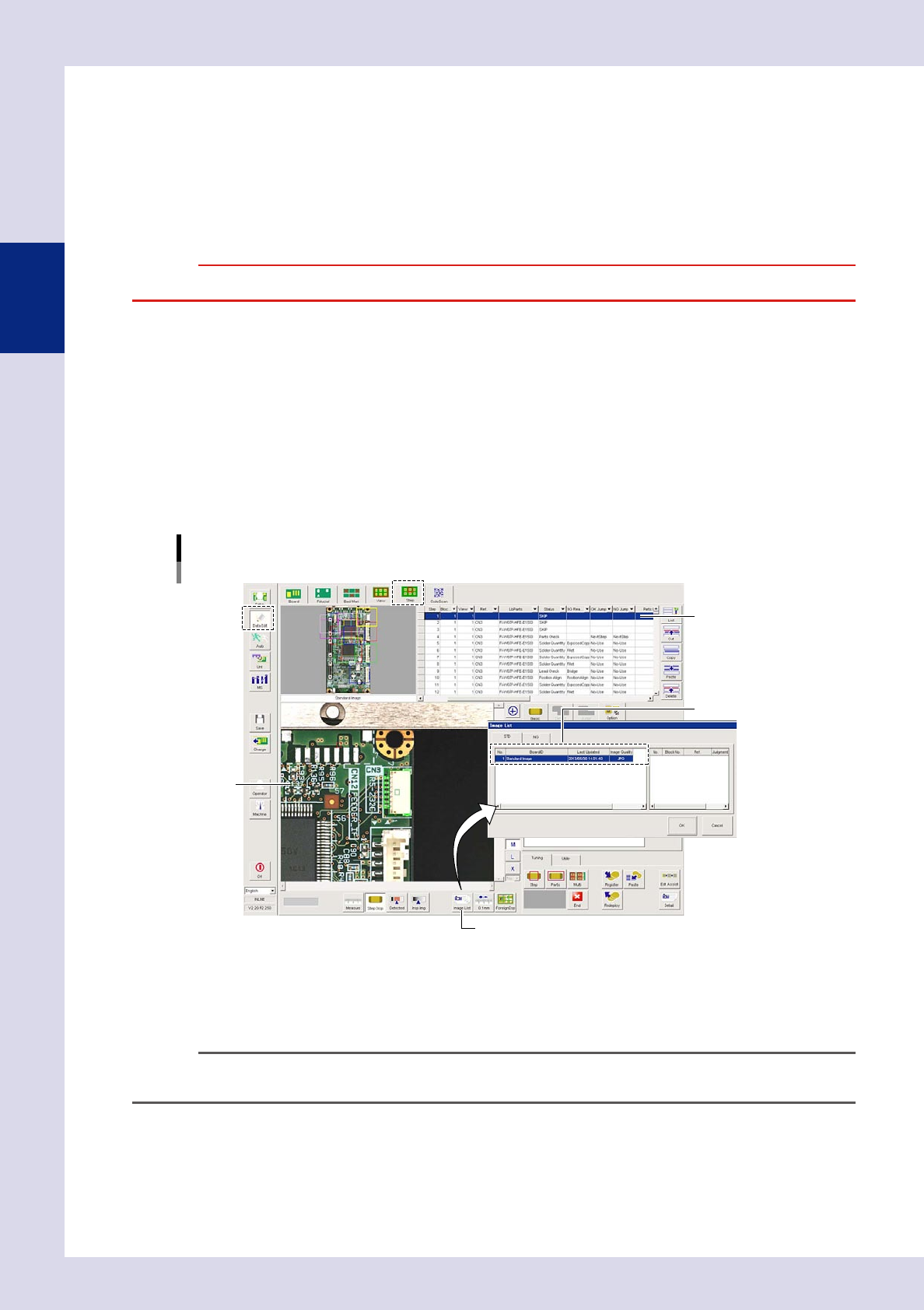
Press the [Data Edit] button and open the "Step" tab.
2
Select a step.
Select the step to be checked from the step data list.
3
Press the [List] button and select a board ID.
By pressing the [List] button, an "Image List" screen appears. Select the board ID to be displayed from
the "Image List" screen, and press the [OK] button. The view screen changes to the selected image.
[Data Edit] – [Step] screen
Board ID selection
[List] button
View image
Select a board ID.
Select a step.
24228-P6-00
4
Change the parameter settings.
Make changes to the parameter settings so that test results are judged correctly. For details, see section
2.7, "Step settings", in this chapter.
n
NOTE
It is possible to set whether to inspect images registered in the image list at the multi-test "Test Condition Setting"
screen. For details on multi-testing, see Chapter 3, "2.4.1 Multi-test", in this manual.