YSI_Prog_E - 第102页
2-31 2 Creating inspection pr ograms 2.6.3 Creating all views and shor tening inspection time Change the view No. to automatically create views for data for whic h steps already exist, and to shorten the inspection head …
2-30
2
Creating inspection programs
n
Saving NG images
View images for which NGs occurred during automatic inspection are automatically saved. By pressing the "NG Image"
tab, a list of saved data appears. To display saved images, press the [List] button in the "Step" tab, open the "Image List"
screen, select a board ID, and then press the [OK] button.
Setting method
Press the [Machine] button to open a settings screen, select "Machine Information"
→
"Installation Setting", and select
"NG Image" from the "Image Setting" - "Image Auto SAVE" drop-down list.
c
When saving NG images, only those view images for which an NG has occurred are saved.
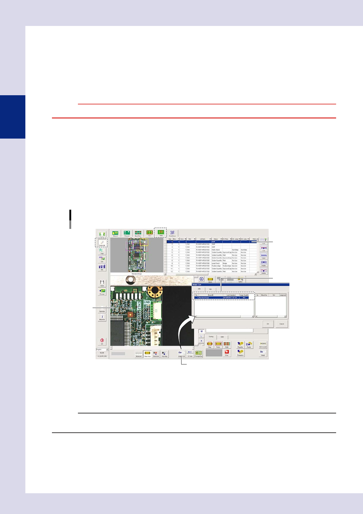
2.6.2 Using view images
Display a saved view image, and check the created inspection program or make changes to parameters.
1
Press the [Data Edit] button and open the "Step" tab.
2
Select a step.
Select the step to be checked from the step data list.
3
Press the [List] button and select a board ID.
By pressing the [List] button, an "Image List" screen appears. Select the board ID to be displayed from
the "Image List" screen, and press the [OK] button. The view screen changes to the selected image.
[Data Edit] – [Step] screen
Board ID selection
[List] button
View image
Select a board ID.
Select a step.
24228-P6-00
4
Change the parameter settings.
Make changes to the parameter settings so that test results are judged correctly. For details, see section
2.7, "Step settings", in this chapter.
n
NOTE
It is possible to set whether to inspect images registered in the image list at the multi-test "Test Condition Setting"
screen. For details on multi-testing, see Chapter 3, "2.4.1 Multi-test", in this manual.
2-31
2
Creating inspection programs
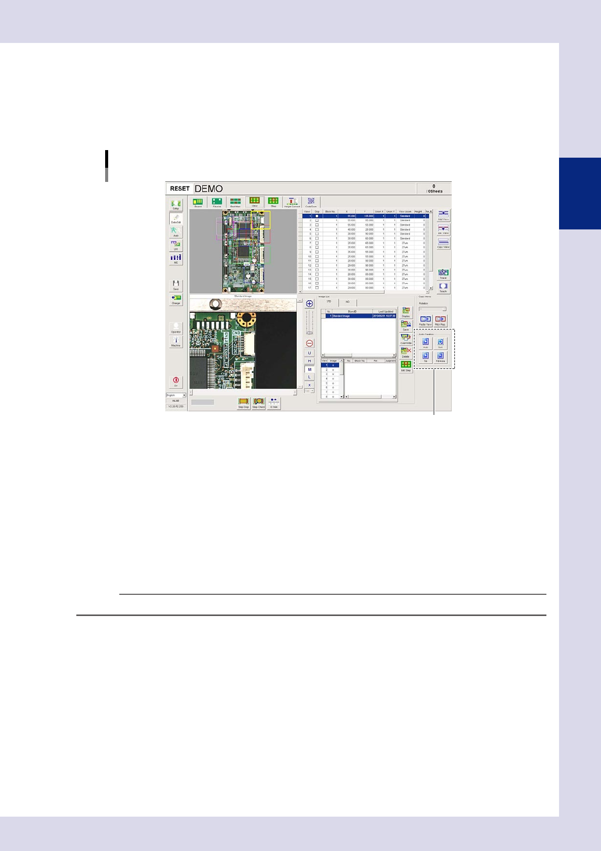
2.6.3 Creating all views and shortening inspection time
Change the view No. to automatically create views for data for which steps already exist, and to shorten the
inspection head movement time.
1
Press the [Data Edit] button and open the "View" tab.
2
Use the auto creation function buttons in the lower right of the screen.
Auto creation function buttons
Auto creation function buttons
24229-P6-00
[Auto] button
Allocates views to include all steps considering step position and size, and adds a view No. to minimize the axis
movement time.
[Tie] button
Creates views uniformly for the entire board.
[Sort] button
Changes the view No. to minimize the axis movement time.
[Fill Area] button
Adds and assigns views to areas on the board to which no views have yet been assigned.
n
NOTE
If editing views with the auto creation function, save the view images.
2-32
2
Creating inspection programs
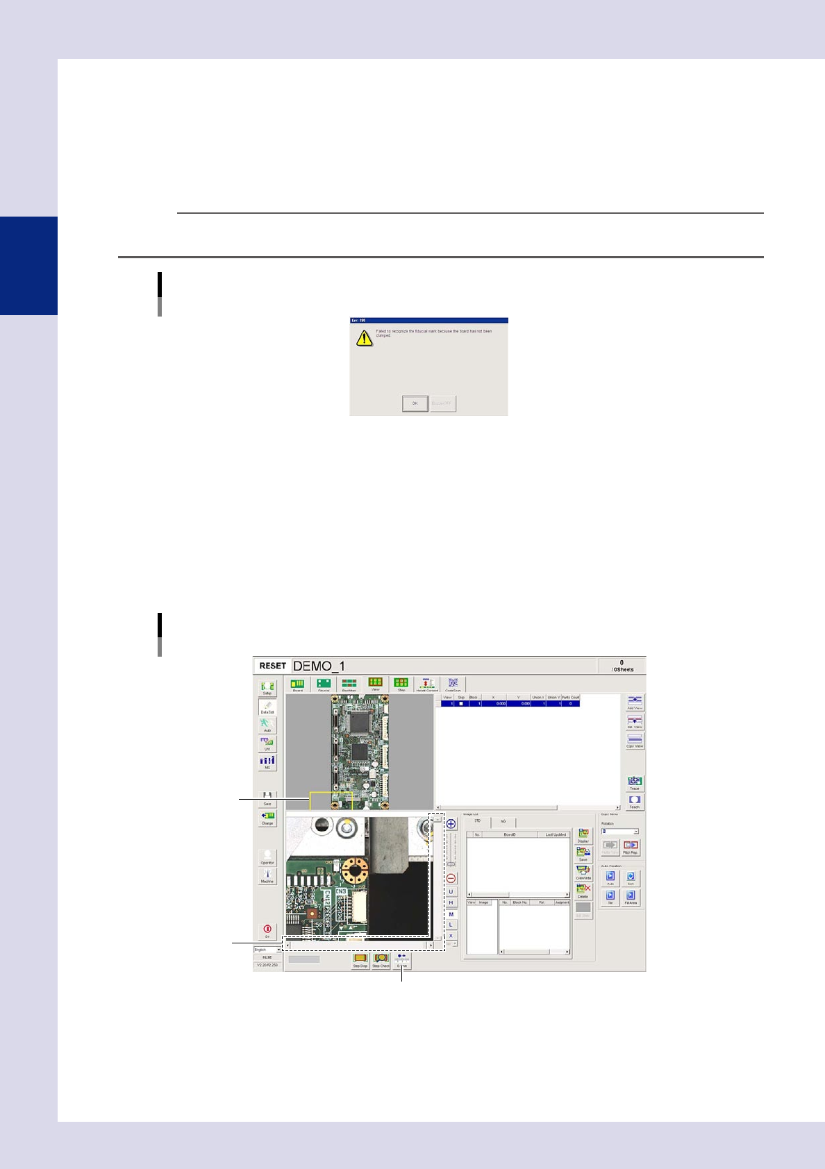
2.6.4 Manual view creation procedure
If unable to convert to an inspection program due to such reasons as having no CAD data, it is necessary to
create views for positions at which inspection is to be performed, and create inspection steps inside these
views. This section describes how to create views. Views cannot be created with the optional iPro offline
software.
1
Press the [Data Edit] button and open the "View" tab.
TIP
If there is no board in the inspection machine, and "View" or "Step" is selected, the following message appears. Press
the [No] button, set the board at the loading entrance sensor detection position, and press the [Change] button
Message
24230-P6-00
2
Move view 1 to the inspection position.
View 1 is created in the lower left of the view radar and is displayed in yellow. Use the following method
to move view 1 to the inspection position.
• Selectview1anddragwiththemouse.
• Usethescrollbar.
• Pressthe[0.1mm]movementpitchbuttontochangethepitch,andthenadjustwiththescrollbar
arrow buttons.
To shorten the camera movement time, allocate views from the edge of the board.
View image
Move view 1.
View 1
Scroll bar
[0.1mm] movement pitch button
24231-P6-00