YSI_Prog_E - 第111页
2-40 2 Creating inspection pr ograms 2.7.2 Step creation procedure Create new steps for parts for whic h libraries hav e not been deployed. T he following example describes the procedure for creating steps to perform fil…
2-39
2
Creating inspection programs
5
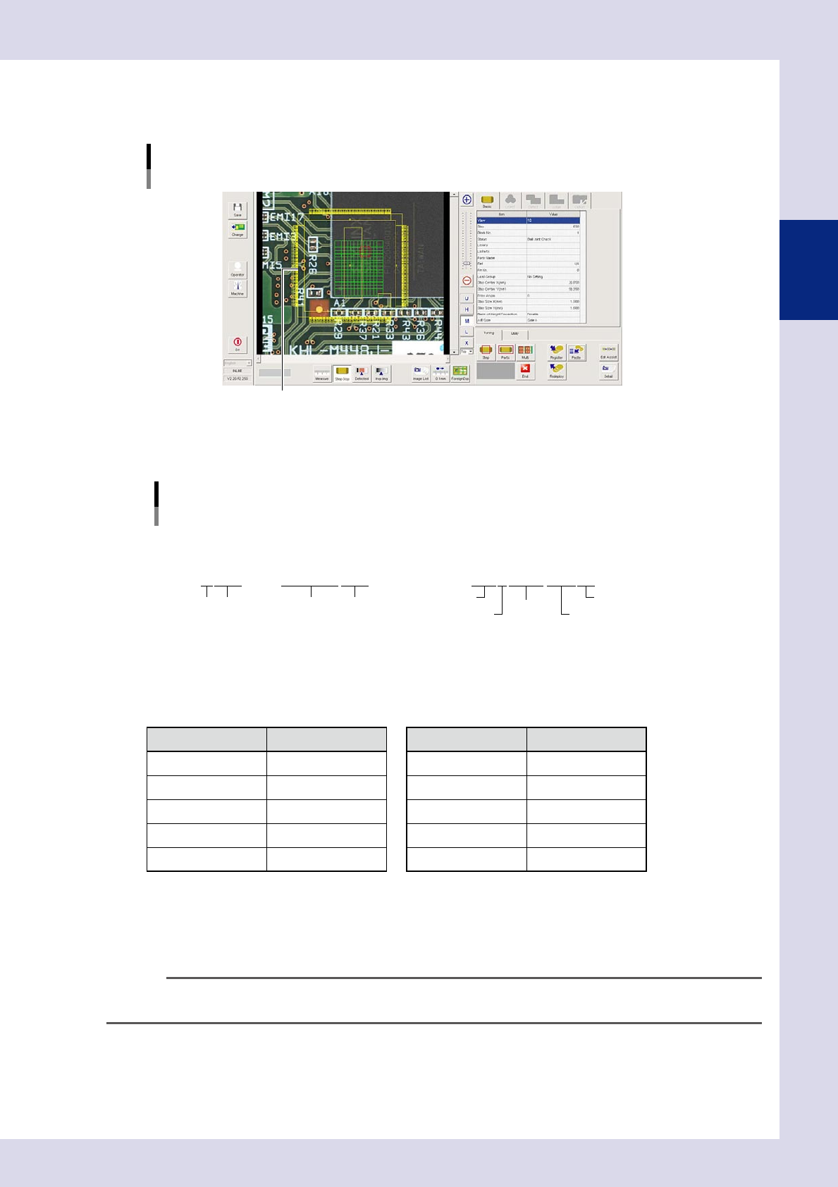
Select the applicable library and press the [OK] button.
The "Library Selection" screen is closed, and the library selected for the view image is displayed in
yellow.
Selected library display
The selected library is displayed.
24257-P6-00
If the applicable library does not exist, select a similar library. Details example names of standard library
names are described below.
R1005 TANTALC1005
SOP4-P1.27-3.5W2.9
Standard library
Lib parts name examples
Example 1: resistor, capacitor, tantalum capacitor Example 2: SOP
(4 pins, pitch: 1.27, lead opposing side width:
3.5 mm, parts body width: 2.9 mm)
Parts type
Parts type
No. of pins
Pitch
Lead opposing side width
Parts body width
Dimensions
Parts type Dimensions
23217-P6-00
• Leadopposingsidewidth(distancefromleadtiptoleadtiponotherside)
W : Square parts with leads on 2 sides or leads on 4 sides
L : Parts with leads on 4 sides, distance in longer direction
The following table shows typical codes.
Parts type Code Parts type Code
Resistor R Network resistor NR
Capacitor C Transistor TR
Mini transistor MTR Diode D
Tantalum capacitor TC Aluminum capacitor AL
Crystal XTL Integrated circuit SOP/QFP/BGA/CSP
6
Paste a library to the mounting position.
1. Move the view image library to the part step position and click.
2. A library parts setting dialog box appears. By pressing the [Yes] button, the library is pasted to the
mounting position.
TIP
If a similar library is pasted, change the parameter settings for that part and register the library. For details on the
registration method, see section 2.7.3, "Registering libraries", in this chapter.
2-40
2
Creating inspection programs
2.7.2 Step creation procedure
Create new steps for parts for which libraries have not been deployed.
The following example describes the procedure for creating steps to perform fillet solder quantity inspection.
1
Press the [Data Edit] button and open the "Step" tab.
2
Create a step.
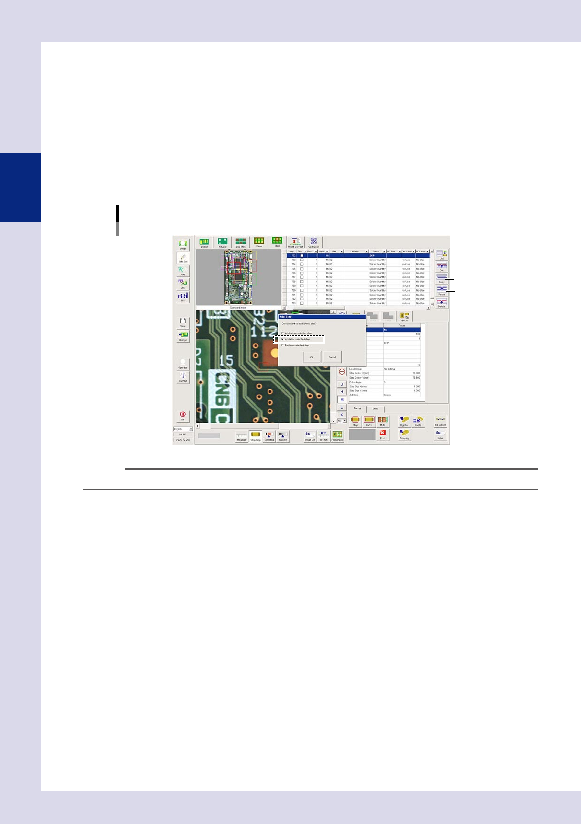
1. Select a part step and press the [Copy] button. If the part has no steps, select the last step in the
relevant view displayed in the basic information field, and then press the [Copy] button.
2. Press the [Paste] button. An "Add Step" dialog box appears. Select "Add after selected step." and
press the [OK] button.
[Data Edit] - [Step] screen
Step creation
[Copy] button
[Paste] button
24240-P6-00
TIP
If copying and pasting steps, the new step is created 0.2 mm to the lower right of an existing step.
3
Set the step frame position and size.
Enclose the object subject to inspection with a step.
Step position setting method
1. Enter the coordinates in "Step Center X, Y (mm)" in the basic parameters.
2. Double-click a step in the step image, increase the step frame thickness, and then move with the
mouse, or press the button to the left of the "Step" field in the step data list, increase the step frame
thickness, and then move with the mouse.
Step size setting method
1. Enter the coordinates in "Step Size X, Y (mm)" in the basic parameters.
2. Double-click a step in step image, increase the step frame thickness, and then drag each side or
corner with the mouse, or press the button to the left of the "Step" field in the step data list, increase
the step frame thickness, and then drag each side or corner with the mouse.
2-41
2
Creating inspection programs
4
In the "Basic" parameter list, set the "Status" (inspection mode).
Select the inspection mode used to inspect the objects in the created step frame.
Select "Solder Quantity Check".
[Data Edit] - [Step] screen
Step creation
Created step
Select "Status"
(inspection mode).
24241-P6-00
TIP
For details on the inspection status and related parameters, see Chapter 4, "Inspection status", in this manual.
5
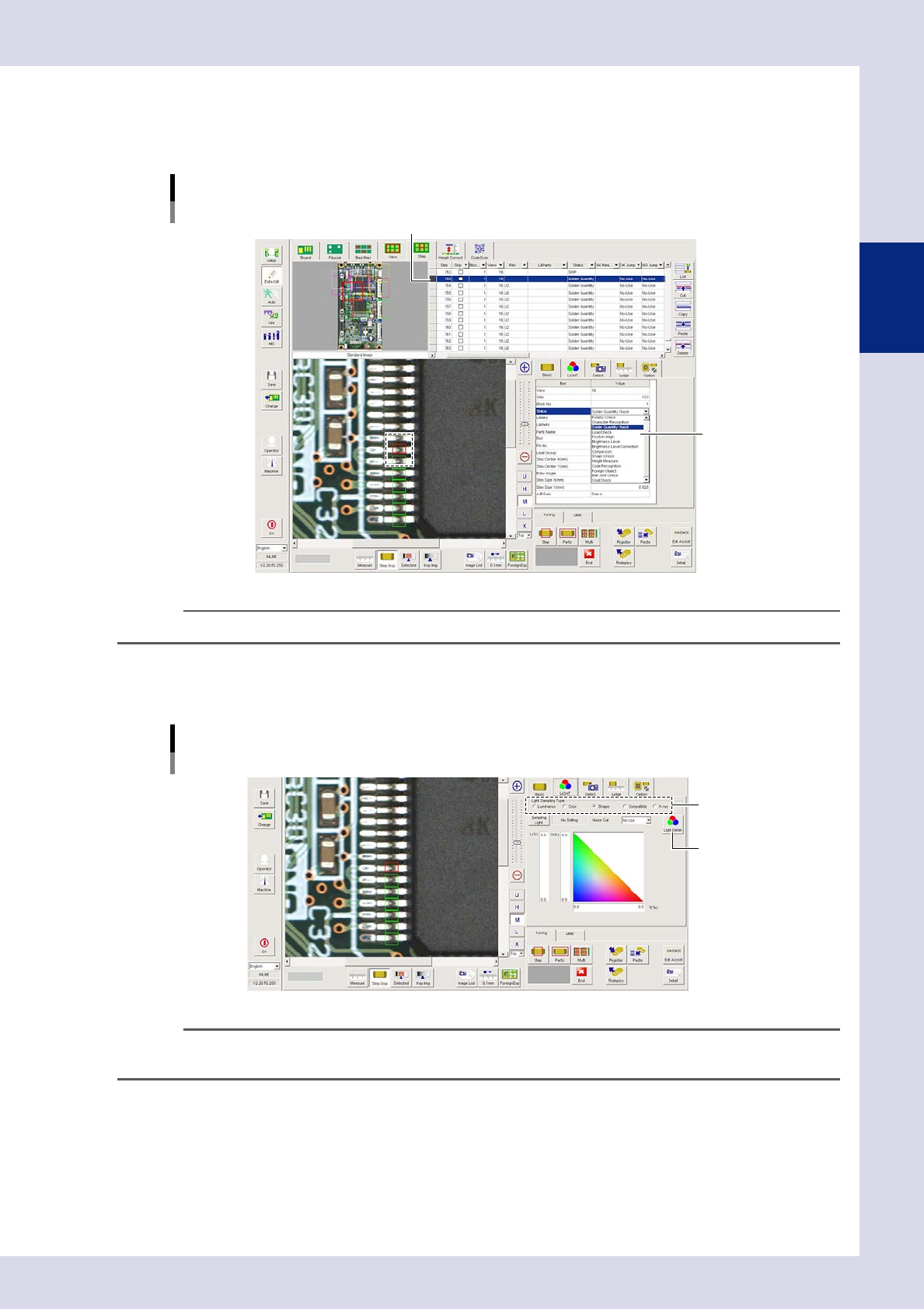
Open the "LIGHT" tab and select the "Light Sampling Type".
If inspecting the fillet solder quantity, click the "Shape" radio button.
[Data Edit] - [Step] screen
[LIGHT] tab settings
Sampling light type
[Light Detail] button
24242-P6-00
TIP
For details on the light sampling type, see Chapter 3, "2.1 Recognition method (based on light sampling type)", in this
manual.