YSI_Prog_E - 第123页
Chapter 3 Step screen Contents 1. Parameters 3- 1 1 1.2 Lighting parameters 3- 2 4 6 9…
2-51
2
Creating inspection programs
Item/button name Function
17 Save Saves changes.
18 Close Closes the library details screen.
19 Parameter Displays all parameters for the selected step. Settings can also be changed here.

Chapter 3 Step screen
Contents
1. Parameters 3-1
1
1.2 Lighting parameters 3-2
4
6
9
2. All functions 3-10
0
2.1.1 Luminance 3-10
2.1.2 Color 3-13
2.1.3 Shape 3-14
2.1.4 X-ray (YSi-X) 3-15
2.1.5 Light detail settings 3-16
2.2 Registering user characters 3-18
2.2.1 Registering new characters 3-18
2.2.2 Editing registered characters 3-21
3
2.4 Step test 3-24
2.4.1 Multi-test 3-24
2.4.2 Measurement results 3-27
3. Editing Assistance 3-28
8
3.2 Copying steps 3-29
3.3 Editing pin Nos. 3-30
3.3.1 Pin No. line editing 3-30
3.3.2 Batch pin No. reassignment 3-31
2
3.5 Pin position editing 3-33
4
4
4.2 Search 3-36
3-1
3
Step screen
1. Parameters
This section describes all parameters set at the "Step" screen. The parameters differ depending on the inspection
status. For details on parameter settings for each inspection status, see Chapter 4, "Inspection status", in this
manual.
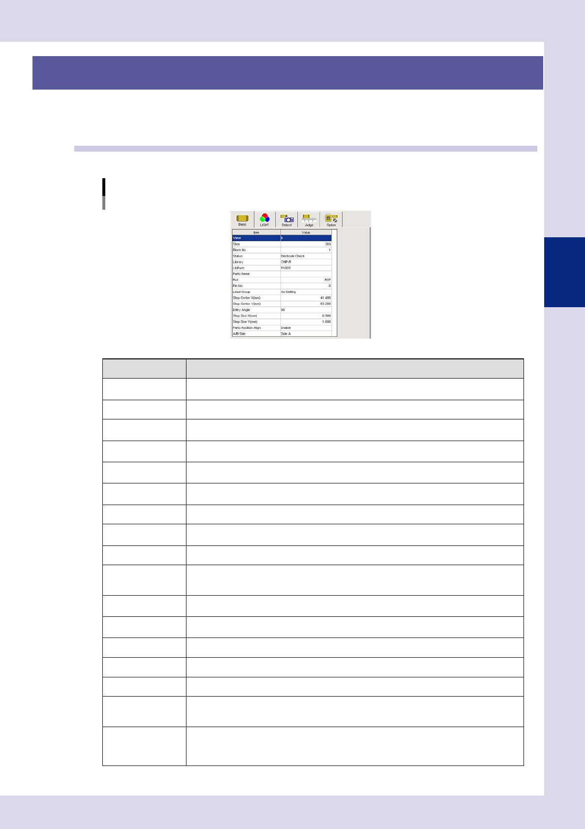
1.1 Basic parameters
Sets and displays step basic information.
Basic parameters
Inspection status "Electrode Check" example
24301-P6-00
Item Description
View
Displays the view No. for the selected step. Jumps to the first step in the view No. selected in the
drop-down list.
Step Displays the selected step No. Enter the jump destination step No. to jump to the step for that No.
block No.
Displays the block No. (multi-board panel block No.) If changing the block No., enter an arbitrary
number.
Status
Displays the inspection status for the selected step. If changing the inspection status, select from
the drop-down list.
Library
If saved to a library, the registered library name is displayed. If changing the library name, enter
an arbitrary library name.
Lib Parts
If saved to a library, the registered library parts name is displayed. If changing the library parts
name, enter an arbitrary library parts name.
Parts Name Displays the name of the selected parts. If changing, enter a parts name.
Ref.
Displayed the reference No. The reference No. can also be entered.
The reference No. is judged as a part for which a single identical step exists.
Pin No. Displays the lead pin No. The pin No. can also be entered.
Lead Group
Displays which direction of the part the leads are on. The lead direction can also be entered.
If "Change-step-size" is selected for the "Position-Align-Method" in the detection conditions, the
lead direction position is not corrected.
Step Center X (mm)
Displays the center X coordinate for the selected step. The step center X coordinate can also be
entered.
Step Center Y (mm)
Displays the center Y coordinate for the selected step. The step center Y coordinate can also be
entered.
Entry Angle Displays the step entry angle. To change, select from the drop-down list.
Step Size X (mm) Displays the X width for the selected step. The X width can also be entered.
Step Size Y (mm) Displays the Y width for the selected step. The Y width can also be entered.
Parts Position Align
This appears when the inspection status is "Parts Check" or "Electrode Check". If "Enable" is
selected, the position of all steps with the same Ref. No. after the relevant step is corrected based
on the recognized displacement.
A/B Side
Entering the "Board Size Height (mm)" in the board parameters and specifying the board surface
sets the height at which X-ray inspection is performed.
Side A: Performs inspection at the board upper surface height.
Side B: Performs inspection at the board lower surface height.