YSI_Prog_E - 第133页
3-10 3 Step screen 2. All functions 2.1 Recognition method (based on light sampling type) T here are four methods av ailable for recognizing inspection objects in order to perform inspection. T hose methods are luminance…
3-9
3
Step screen
1.5 Option parameters
These parameters specify option settings for inspection steps.
TIP
The displayed parameters differ depending on the inspection status. For details on parameter settings for each status,
see Chapter 4, "Inspection status", in this manual.
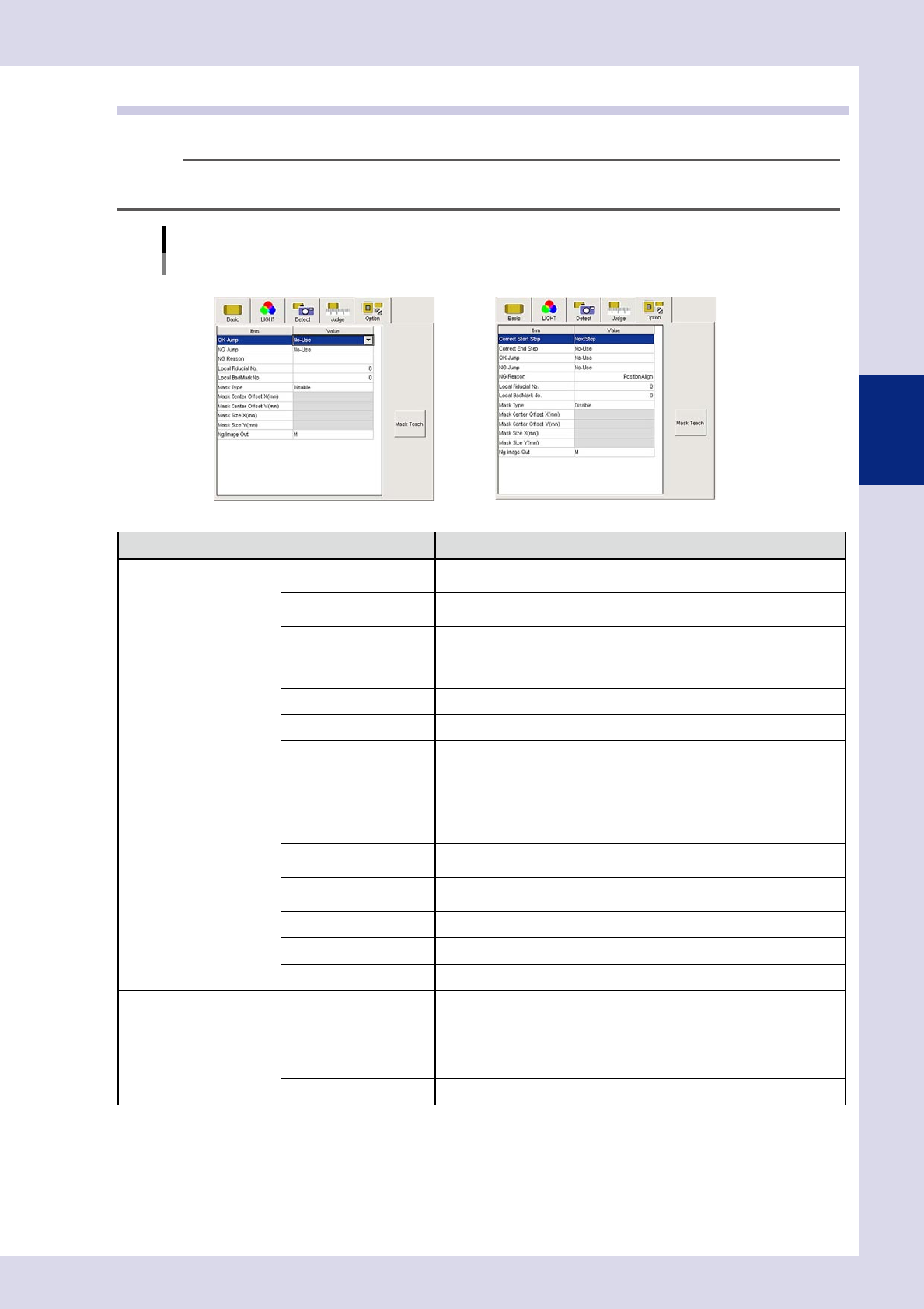
Option parameters
Inspection status "Electrode Check", "Position Align" example
NElectrode Check NPosition Align
24305-P6-00
Inspection status Item Details
STD.
Parts Check
Electrode Check
Polarity Check
Character Recognition
Solder quantity check
Lead Check
Position Align
Brightness level
Brightness Level Correction
Comparison
Shape Check
Height Measure
Code Recognition
Foreign Object
Ball Joint Check
Void Check
OK jump
Specify the step No. to be inspected next when the judgment result is
"OK".
NG jump
Specify the step No. to be inspected next when the judgment result is
"NG".
NG Reason
Enter the NG (fail) reason to display during automatic inspection when the
judgment result is "NG".
Maximum number of characters: 14 alphanumeric characters or 7 full-width
characters
Local Fiducail No. Sets the local Fid No.
Local BadMark No. Sets the local Bad No.
Mask Type
• Disable
Does not perform inspection mask function.
• Include
Always detects areas enclosed with a mask.
• Exclude
Does not include areas enclosed by mask in the inspection.
For details, see section 2.3, "Mask function", in this manual.
Mask Center Offset
X(mm)
Sets the X offset amount from the step center position to the mask center
position.
Mask Center Offset
Y(mm)
Sets the Y offset amount from the step center position to the mask center
position.
Mask Size X(mm) Sets the inspection mask X direction size.
Mask Size Y(mm) Sets the inspection mask Y direction size.
Ng image Out Sets the lighting when sent to the Repair Station (option).
Polarity Check Inspect Only First Parts
This setting can only be specified for "Character Recognition" and
"Electrode Check".
Inspection steps set to "Enable" are only inspected on the first board after
reading the inspection program.
Position Align
Correct Start Step Specifies the first step No. in the range subject to alignment.
Correct End Step Specifies the last step No. in the range subject to alignment.
[Mask Teach] button
Moves the mask area and changes the size of it. For details on operation, refer to section 2.3, "Mask function", in this
chapter.
3-10
3
Step screen
2. All functions
2.1 Recognition method (based on light sampling type)
There are four methods available for recognizing inspection objects in order to perform inspection. Those
methods are luminance, color, shape, and X-ray. Select the image to be used for inspection, and then set the
threshold value to show the object to be inspected in red.
2.1.1 Luminance
Samples detection objects in region of specified luminance, and uses them as the object of inspection. Open
the "LIGHT" tab and select "Luminance" for the "Light Sampling Type".
1
Selects the sampling light.
Sampling light is the lighting used for inspection. Use the following procedure to select the sampling
light.
1. Press the [Light Detail] button to open the "Luminance" screen.
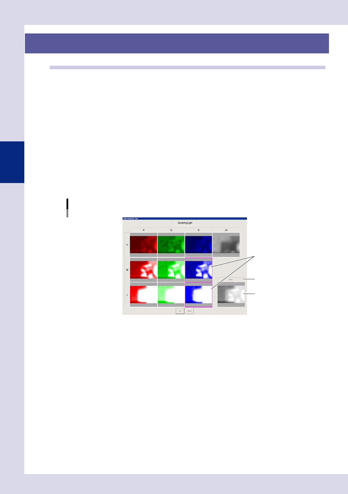
2. Press the [Sampling Light] button to open a sampling light type screen, and select up to two images
that show the inspection object with good contrast. The name of the selected images and
composite image of the selected images appears in the lower right. This image is used for inspection.
3. Press the [OK] button to save the settings.
Light Sampling Type: Luminance
Sampling light.
Select the image(s).
Composite image
Image name
24306-P6-00
3-11
3
Step screen
2
Selects the reduced light.
Reduced light is lighting for images excluded from images used for inspection. (Reduced lighting does
not have to be selected.) Use the following procedure to select the reduced light.
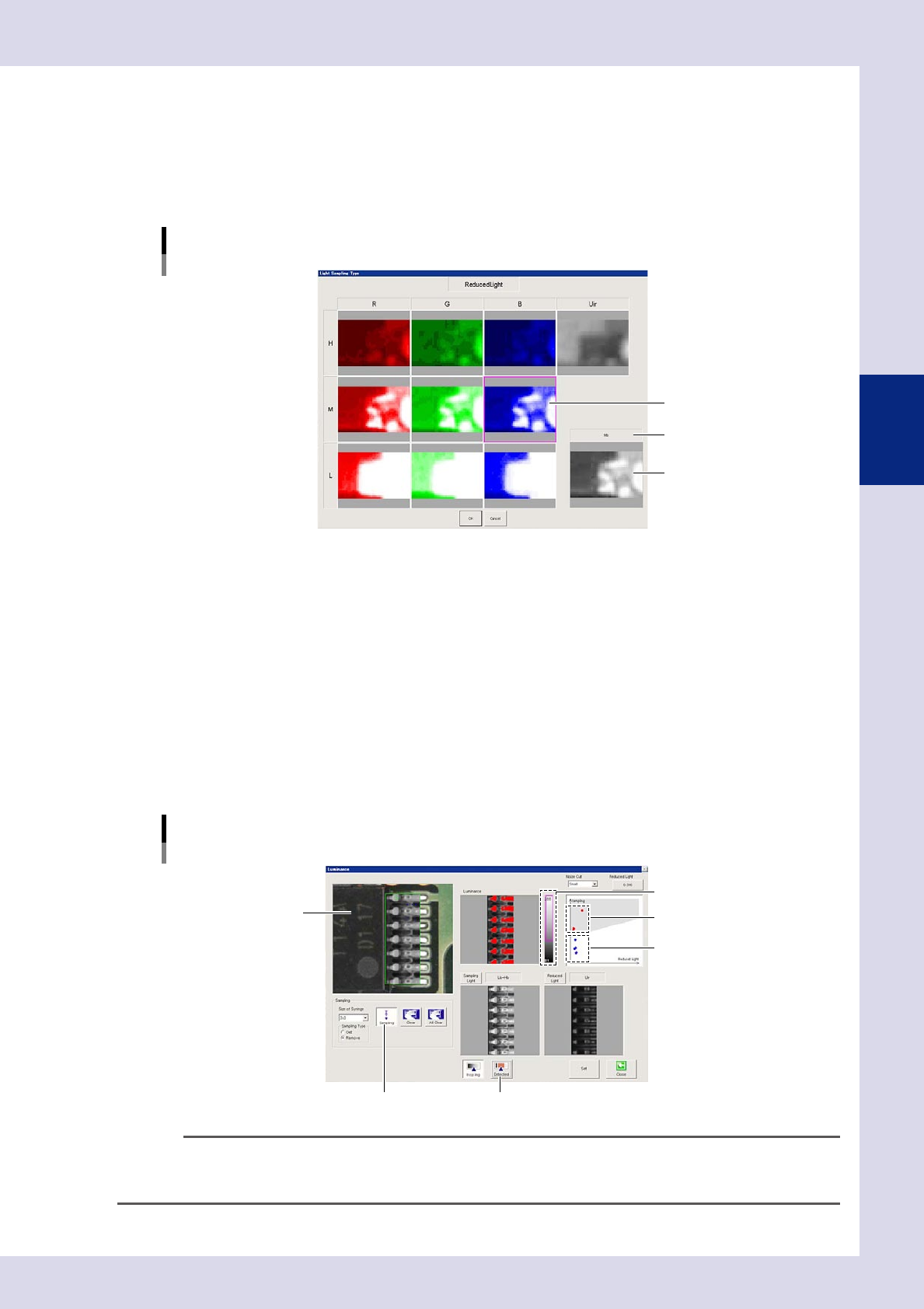
1. Press the [Reduced Light] button at the "Luminance" screen to open the light sampling type screen.
2. Select one image with good contrast other than the object to be inspected, and press the [OK]
button.
Light Sampling Type: Luminance
Reduced light
Select the image.
Selected image
Image name
24307-P6-00
3
Set the threshold value.
1. Press the [Sampling] button.
2. Click the location to be detected in the upper left image. The clicked luminance is plotted with red
dots in the upper right image.
3. Select the "Sampling Type" - [Remove] radio button, and click the location that is not to be
detected. The clicked luminance is plotted with blue dots in the upper right image.
4. Press the [Sampling] button again to end sampling.
5. Press the [Detected] button to verify the area sampled and shown in red in the upper left image. The
luminance area shown in gray in the drawing upper right is sampled and shown in red. If the
threshold slide bar is moved or reduced light is selected, adjust by dragging the gray area and
changing the angle so that only the detection object is shown in red. If the gray area is changed
and the angle changed, the reduced light magnification is also changed.
Light Sampling Type: Luminance
Threshold value
[Sampling] button [Detected] button
Click the detection location.
Detected location (red)
Threshold slide bar
Undetected location (blue)
24308-P6-00
TIP
Adjustment is also possible without performing sampling by adjusting the threshold slide bar or changing the angle of
the gray area. The reduced light magnification value can be changed by pressing the [Reduced Light] button and
entering the magnification directly.