YSI_Prog_E - 第136页
3-13 3 Step screen 2.1.2 Color Samples detection objects in region of specified color , and uses them as the object of inspection. 1 Selects the sampling light. 1. Select "Color" for the sampling light type, an…
3-12
3
Step screen
4
Press the [Set] button to save the settings.
By pressing the [Set] button, the display returns to the "Step" screen.
n
Multiple threshold value settings
If there are differences in inspection object luminance due to differences in part lots, inspection can be performed by
setting four different threshold values for a single step.
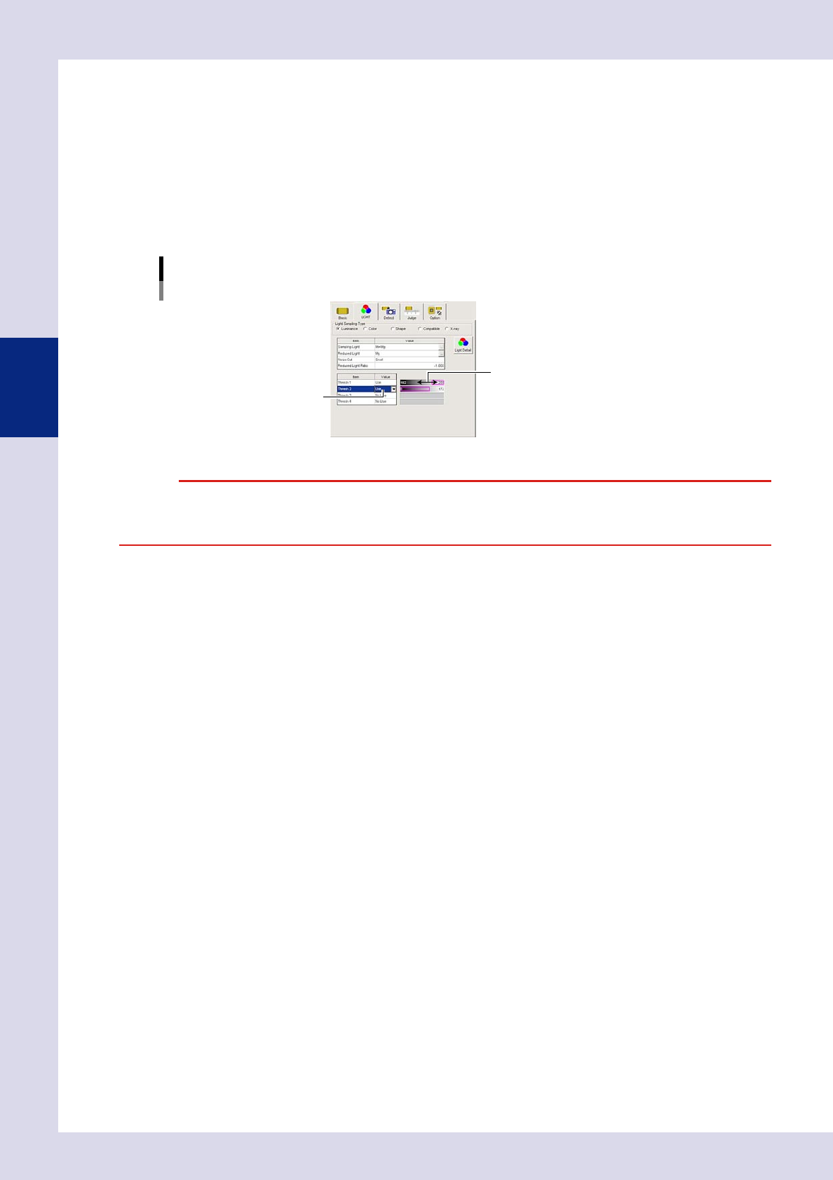
1. Press the "LIGHT" tab at the [Data Edit] - "Step" screen.
2. Set "Thresh 2", "Thresh 3", and "Thresh 4" to "Use" only for the number of set threshold values.
3. Use the threshold value setting bar to display only the inspection object in the step screen in red.
Light Sampling Type: Luminance
Multiple threshold value settings
Threshold value setting bar
Set to "Use".
24309-P6-00
c
the test is performed using only the selected threshold value.
3-13
3
Step screen
2.1.2 Color
Samples detection objects in region of specified color, and uses them as the object of inspection.
1
Selects the sampling light.
1. Select "Color" for the sampling light type, and then press the [Light Detail] button.
2. Press the [Sampling Light] button at the color screen, select one image from the sampling light list
that shows the inspection object with good contrast, and press the [OK] button.
Light Sampling Type: Color
Sampling light.
Select the image.
24310-P6-00
2
Set the threshold value.
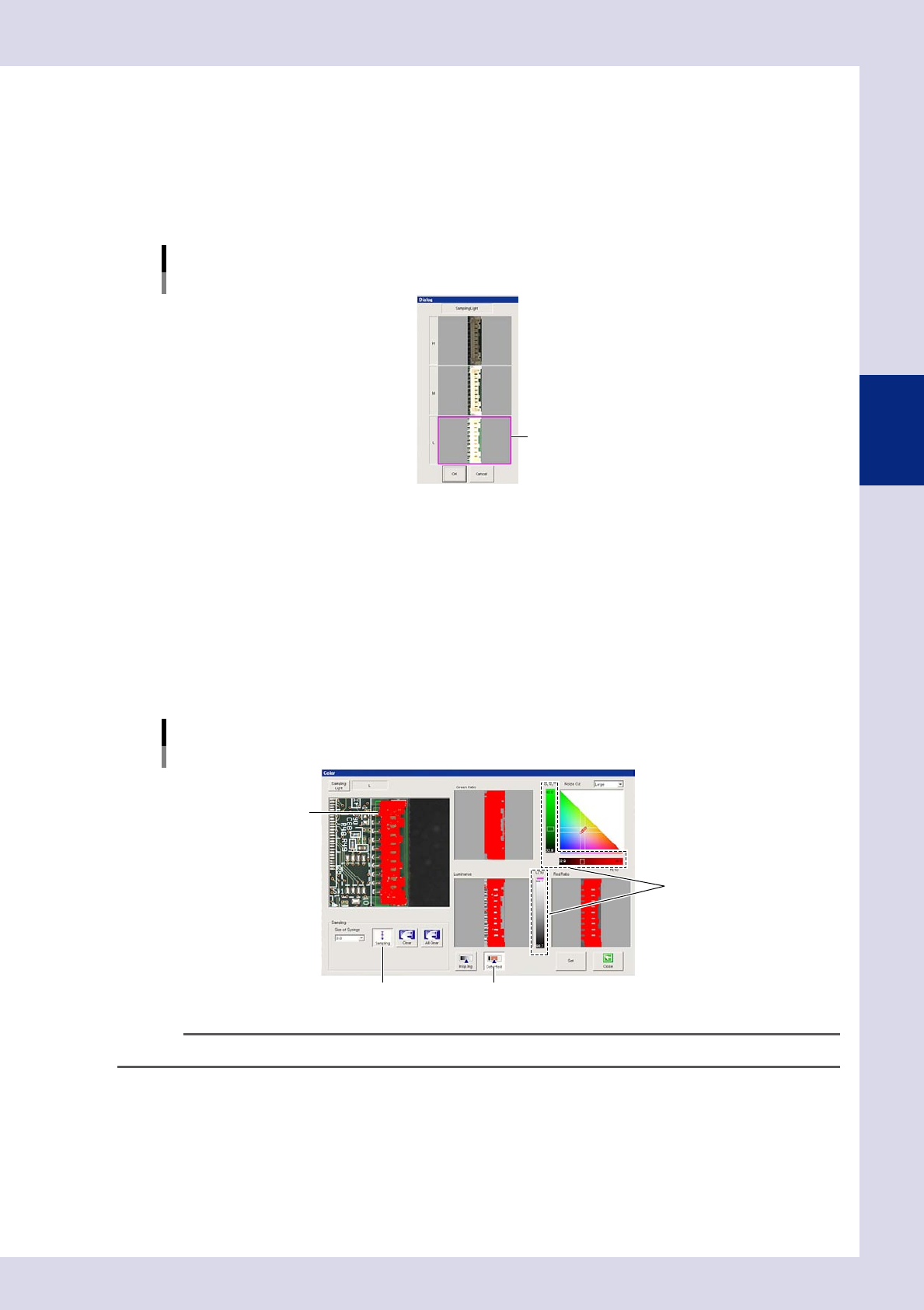
1. Press the [Sampling] button.
2. Click the location to be detected in the upper left image. The location with same color as the
clicked location is shown in red. When a large area of the part being sampled turns red, press the
[Sampling] button again to end sampling.
3. Press the [Detected] button to verify the area sampled and shown in red in the upper left image.
4. Move the three threshold slide bars to adjust the threshold value until only the inspection object is
shown in red. The area shown in red with Green Ratio, Red Ratio, and Luminance images is shown in
red in the upper left of the image.
Light Sampling Type: Color
Threshold value
[Sampling] button [Detected] button
Threshold slide bar
Click the detection location.
24311-P6-00
TIP
The threshold value and gray area angle can also be adjusted without performing sampling.
3
Press the [Set] button to save the settings.
3-14
3
Step screen
2.1.3 Shape
1
Selects the sampling light.
1. Select "Shape" for the sampling light type, and then press the [Light Detail] button.
2. To cancel the existing settings, press the [All Clear] button.
3. Press the [Sampling Light] button at the shape screen, and select one image from the sampling light
list that shows the inspection object with good contrast. (Hr+Mg+Lb Ver2 should normally be
selected.)
4. Press the [OK] button.
Light Sampling Type: Shape
Sampling light.
Select the image.
24312-P6-00
2
Set the threshold value.
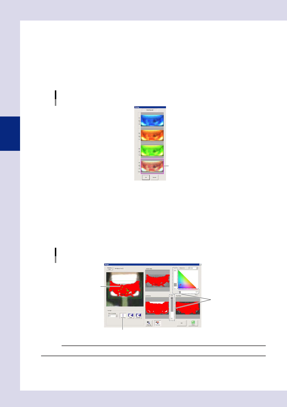
1. Press the [Sampling] button.
2. Click the location to be detected in the upper left image. The location with same color as the
clicked location is shown in red.
3. When most of the part being sampled turns red, press the [Sampling] button again to end sampling.
4. Move the three threshold slide bars to adjust the threshold value until only the inspection object is
shown in red. The area shown in red with Green Ratio, Red Ratio, and Luminance images is shown in
red in the upper left of the image.
Light Sampling Type: Shape
Threshold value
[Sampling] button
Threshold slide bar
Click the detection location.
24313-P6-00
TIP
The threshold value and gray area angle can also be adjusted without performing sampling.
3
Press the [Set] button to save the settings.