YSI_Prog_E - 第145页
3-22 3 Step screen n Registered character matching T his section describes the procedure for checking how well the selected c haracter matches the registered c haracter . 1. Adjust the threshold value and perform c harac…
3-21
3
Step screen
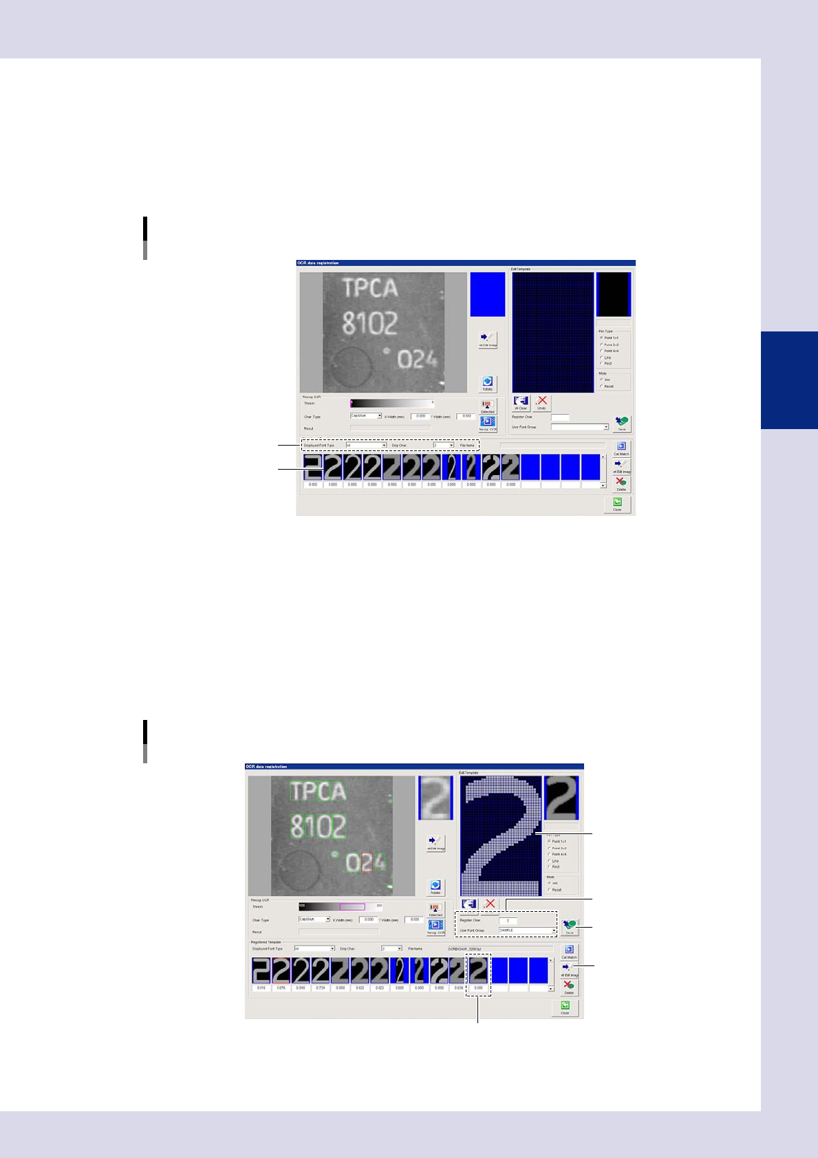
2.2.2 Editing registered characters
When registering user characters, characters that have already been registered can be edited and then
registered in a template. The procedure is as follows.
1
Select the character to be edited.
1. Select "All" for the "Displayed Font Type", and select the character to be edited at "Disp Char."
2. Select the character to be edited from the font list.
"OCR data registration" screen
Select the character to be edited.
Select the displayed font type
and display character.
Select the font.
24325-P6-00
2
Press the [Set Edit Image] button.
The selected character is displayed in the "Edit Template" screen.
3
Edit the image.
Select the pen type and mode to edit the image.
4
Register the character.
When editing is complete, set the character to be registered and the user font group, and then press
the [Save] button. When registration is complete, the character is displayed in the registered template
character list.
"OCR data registration" screen
Registered image editing
[Save] button
Display the registered character.
Correct the image.
Set the image to be
registered and group.
[Set Edit Image] button
24326-P6-00
3-22
3
Step screen
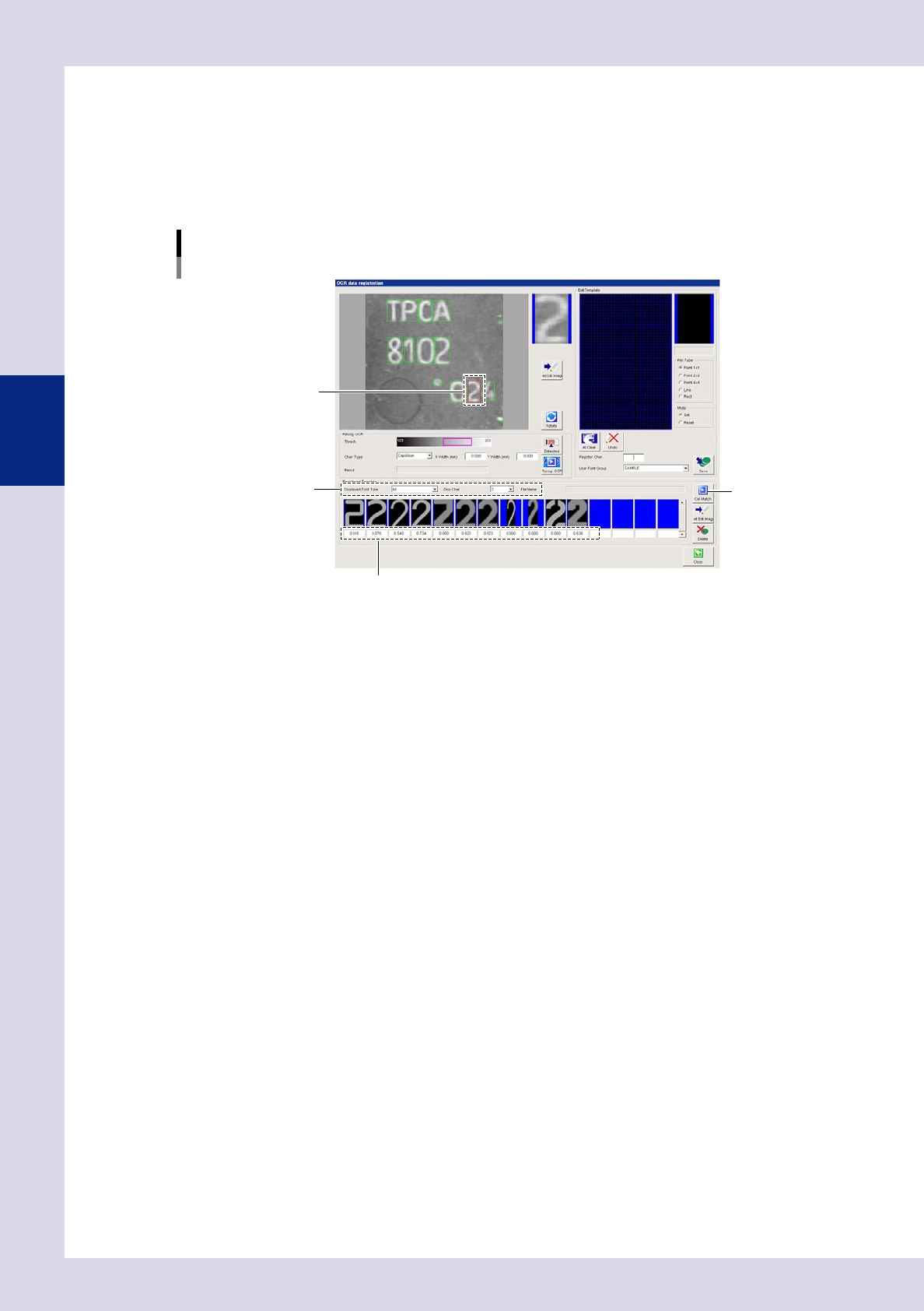
n
Registered character matching
This section describes the procedure for checking how well the selected character matches the registered character.
1. Adjust the threshold value and perform character recognition.
2. Select the character to check for a match.
3. By pressing the [Cal. Match] button, the match between the character to be checked and the registered character is
displayed.
"OCR data registration" screen
Match check
[Cal. Match] button
Displays the match.
Select the displayed font
type and display character.
Select the character.
24324-P6-00
3-23
3
Step screen
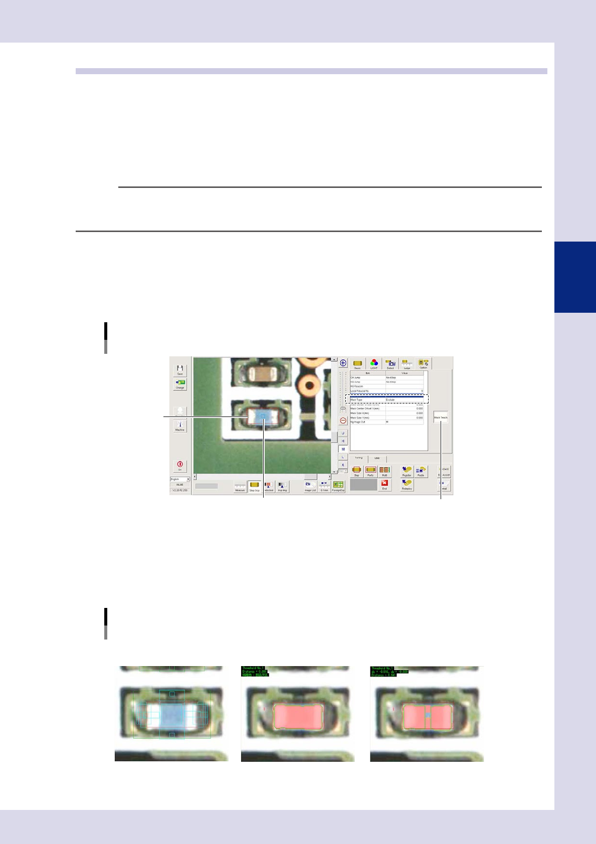
2.3 Mask function
The mask function involves creating a mask area inside a step, and specifying whether or not to always detect
the created mask area when performing inspection. If, for example, the inspection status is "Parts Check", and
the printed characters on the top of the parts cannot be recognized, using this function, an inspection object
exclusion mask is created at the character position and inspection is performed. Furthermore, if the inspection
status is "Electrode Check" and the electrode and parts are detected simultaneously, inspection can be
performed by creating an inspection object exclusion mask in the center of the parts. This procedure describes
an example in which the inspection status is chip part "Electrode Check", the electrode and part are detected
simultaneously, and an inspection object exclusion mask is created in the center of the parts.
TIP
The mask function is valid for the following inspection statuses.
parts
check, electrode check, polarity check, character recognition, solder quantity check, lead check, position
align, brightness level, shape check
1
Select an electrode check step.
Select "Exclude" for the "Mask Type" in the option parameters. By selecting "Exclude", the mask area is
never detected.
2
Press the [Mask Teach] button.
The mask frame (blue) is displayed inside the step frame (red).
"Option" tab
Select the mask type.
[Mask Teach] button
Step frame (red)
Mask frame (blue)
24327-P6-00
3
Align the mask frame size and position.
Drag the mask frame with the mouse to align the size and position with the target area.
The size and position can also be aligned by entering values for "Mask Center Offset X, Y" and "Mask Size
X, Y" in the option parameters.
The following images represent an example of a parts check with inspection object mask set in the
resistor body position.
Mask setting image example
M lighting Mask type: Disable
Test result: NG
Mask type: Exclude
Test result: OK
24328-P6-00