YSI_Prog_E - 第153页
3-30 3 Step screen 3.3 Editing pin Nos. 3.3.1 Pin No. line editing T his function is used when assigning pin Nos. to the leads on all sides of leaded parts. 1 Select a step. Select all steps at which pin Nos. are to b e …
3-29
3
Step screen
3.2 Copying steps
This function is used when creating multiple selected steps in the X and Y directions with arbitrary pitch.
1
Select a step.
Select the steps to be copied at the "Step" screen.
Multiple steps can also be copied by dragging with the mouse.
2
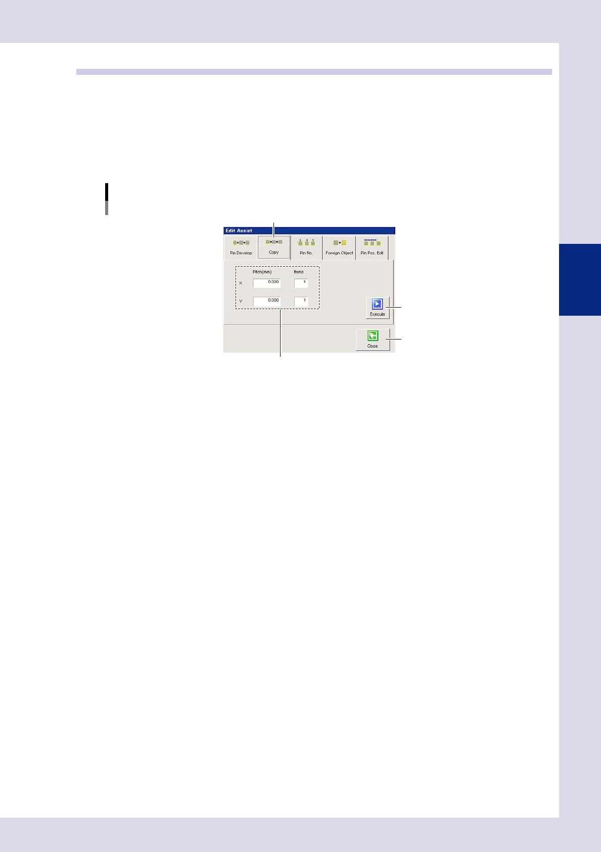
Press the [Edit Assist] button and open the "copy" tab.
A screen used to set step copy conditions appears.
Editing assistance
Copying
Step 4
[Execute] button
[Close] button
"copy" tab
24334-P6-00
3
Enter the pitch and number of items.
If copying the X direction (horizontal), enter the pitch and number of items after copying in the X field.
By entering a positive value for pitch, steps are copied in the right direction, and by entering a negative
value, steps are copied in the left direction. If copying the Y direction (vertical), enter the pitch and
number of items after copying in the X field. By entering a positive value for pitch, steps are copied in
the upward direction, and by entering a negative value, steps are copied in the downward direction.
4
Press the [Execute] button.
Copied steps are displayed in a step image.
5
Press the [Close] button to end deployment.
3-30
3
Step screen
3.3 Editing pin Nos.
3.3.1 Pin No. line editing
This function is used when assigning pin Nos. to the leads on all sides of leaded parts.
1
Select a step.
Select all steps at which pin Nos. are to be assigned at the "Step" screen.
2
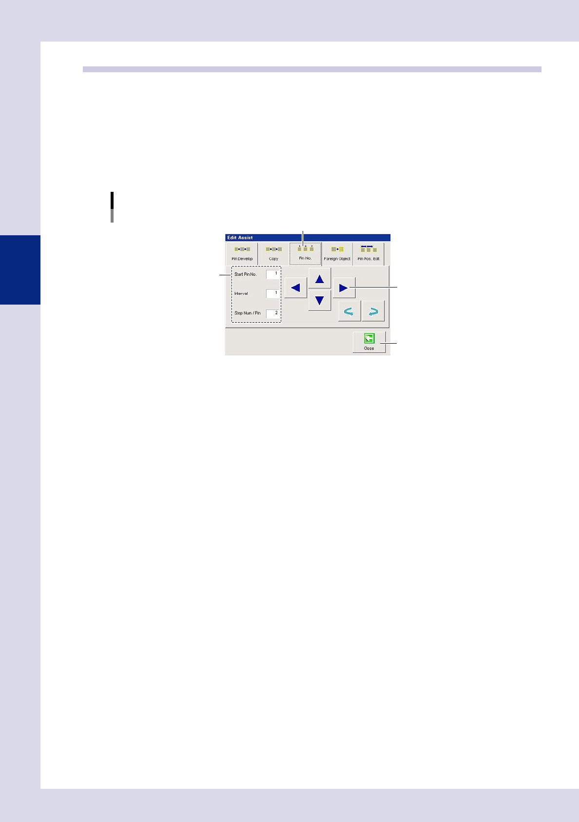
Press the [Edit Assist] button and open the "Pin No." tab.
A screen used to edit step pin Nos. appears.
Editing adjustment
Editing pin Nos.
"Pin No." tab
[Close] button
Step 3
Step 4
24335-P6-00
3
Set all conditions.
Start Pin No.
Enter the first pin No. from among the selected leads.
Interval
Enter the interval for the pin No. being assigned.
Step Num / Pin
Enter the number of steps required to inspect one pin.
4
Press the arrow buttons.
Press the arrow button facing in the direction of the number being assigned.
The pin No. is entered in "Pin No." in the basic parameters.
5
Press the [Close] button to end deployment.
3-31
3
Step screen
3.3.2 Batch pin No. reassignment
This function is used when reassigning pin Nos. clockwise or counterclockwise at one time for leaded parts for
which pin Nos. have already been set.
n
Settings prior to assignment
It is necessary to specify the following settings in order to reassign pin Nos. correctly.
Basic parameters
Pin No.
Pin Nos. are not reassigned for steps with pin No. 0.
Lead Group:
Select the lead position for the part from the drop-down list.
Up (N) : Steps on upper side of part
Down (S ): Steps on lower side of part
Right (E) : Steps on right side of part
Left (W) : Steps on left side of part
1
Select the start pin.
Refer to the following table and select the start pin (step) for pin No. reassignment from the view screen.
Start pin (step)
Step position Clockwise Counterclockwise
Up (N) Left edge step Right edge step
Down (S) Right edge step Left edge step
Right (E) Upper edge step Lower edge step
Left (W) Lower edge step Upper edge step
2
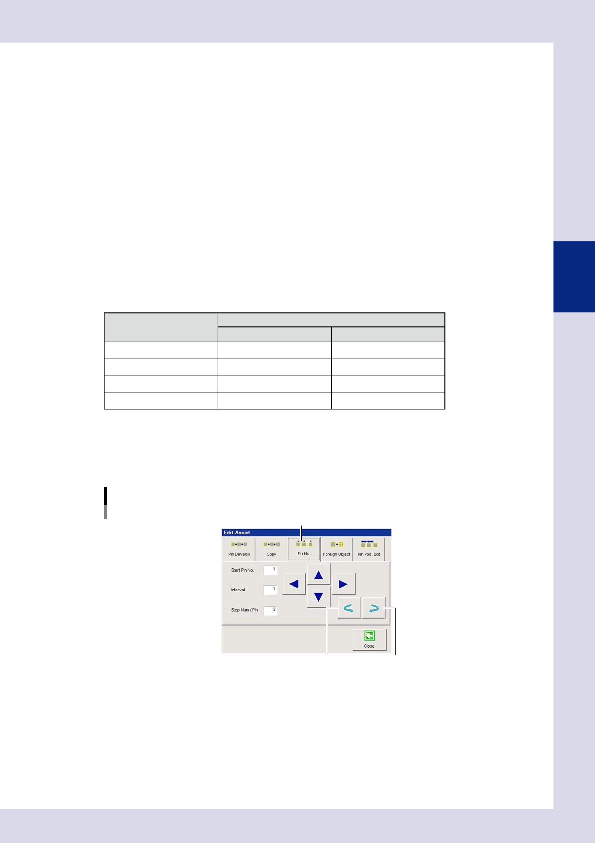
Press the [Edit Assist] button and open the "Pin No." tab.
3
Select the reassignment direction.
Press the clockwise arrow button or counterclockwise arrow button based on the reassignment
direction.
Editing assistance
Pin No. editing - Batch pin No. reassignment
"Pin No." tab
Counterclockwise arrow button Clockwise arrow button
24336-P6-00
Clockwise arrow button
Reassigns pin Nos. clockwise from the start pin No.
Counterclockwise arrow button
Reassigns pin Nos. counterclockwise from the start pin No.
4
Press the [Close] button to end deployment.