YSI_Prog_E - 第160页
Chapter 4 Inspection status Contents 1. Inspection status 4- 1 1.1 Parts Check 4- 2 1.2 Electrode Check 4- 5 1.3 Polarity Check 4- 8 1.4 Character Recognition 4-1 1 1.5 Solder Quantity Check 4-1 4 1.6 Lead Check 4-1 6 1.…
3-36
3
Step screen
4.2 Search
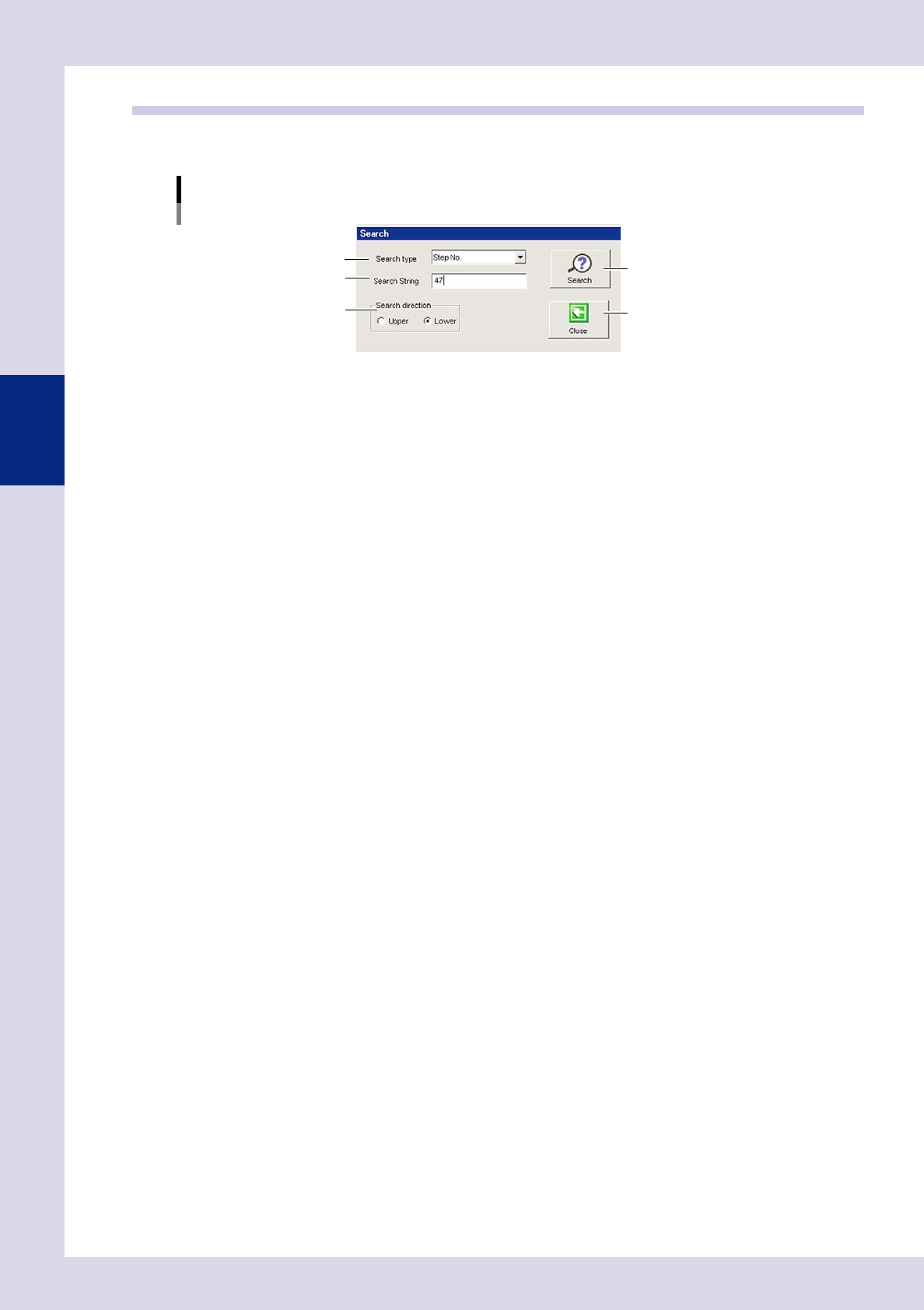
By pressing the [Search] button at the "Utility" tab, a "Search" screen appears. This screen is used to search for
the next step matching the set search conditions.
"Search" screen
Step 2
Step 3
Step 1
[Search] button
[Close] button
24340-P6-00
1
Specify the search type.
Select from "Step No.", "View step", "Ref. No.", "Status", "Parts Name", "Block No."
2
Specify the search character string.
Enter the search content details.
3
Select the search direction.
Select the direction with the radio buttons.
4
Press the [Search] button.
Each time this button is pressed, the next step matching the search conditions is displayed on the step
screen.
5
Press the [Close] button to end deployment.

Chapter 4
Inspection status
Contents
1. Inspection status 4-1
1.1 Parts Check 4-2
1.2 Electrode Check 4-5
1.3 Polarity Check 4-8
1.4 Character Recognition 4-11
1.5 Solder Quantity Check 4-14
1.6 Lead Check 4-16
1.7 Position Correction 4-19
2
1.9 Comparison 4-25
1.10 Shape Check 4-28
1.11 Code Recognition 4-31
3
6
9
2
4-1
4
Inspection status
1. Inspection status
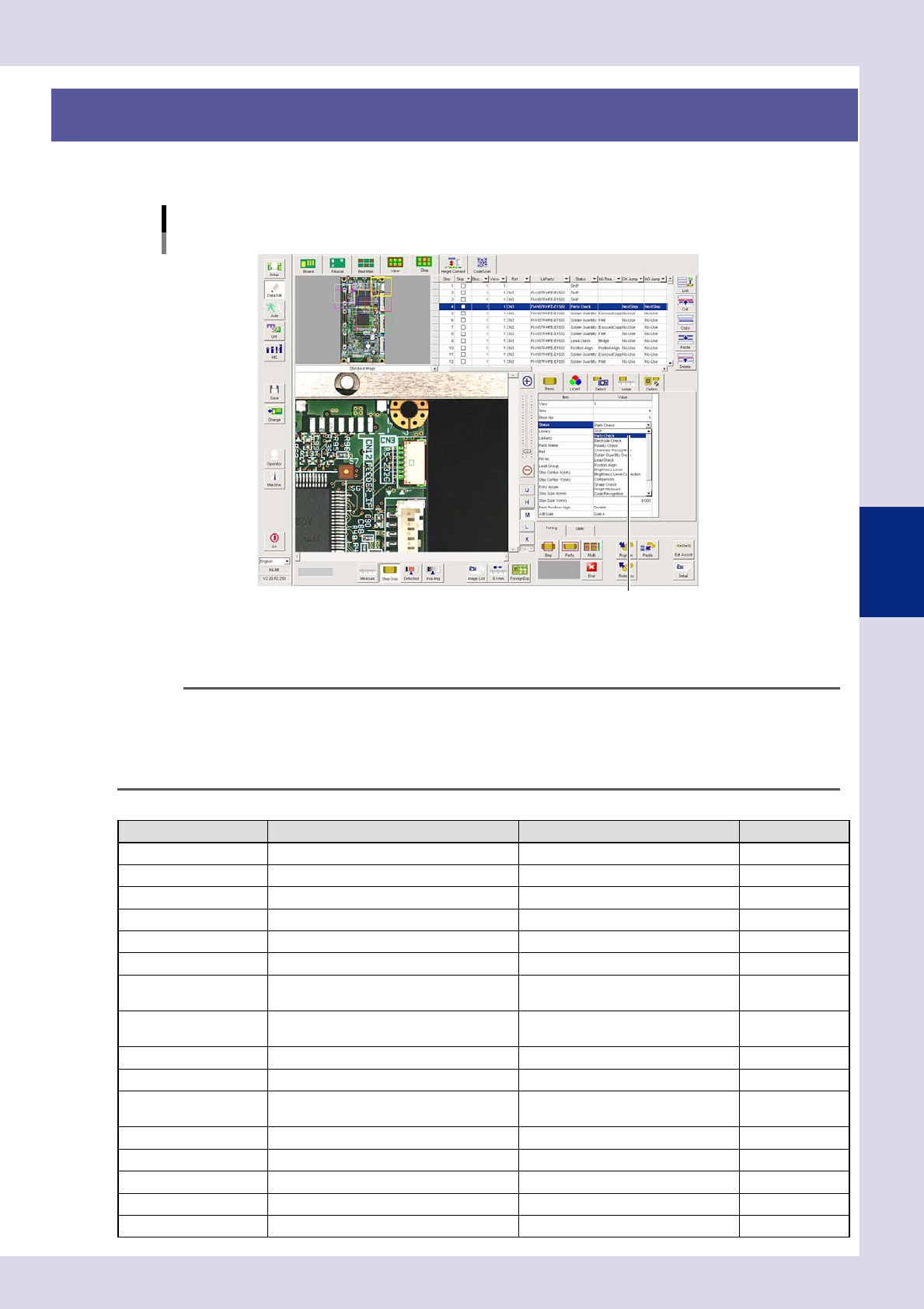
Items to be inspected are classified into "Status" items (inspection modes), and an inspection mode must be
specified for each "step" on the [Data Edit] – [Step] screen.
[Data Edit] - [Step] - [Basic] screen
Status (inspection mode) setting
Select inspection mode from this drop-down list.
24401-P6-00
From the "Status" drop-down list, select the inspection mode for the inspection item. The setting contents differ
depending on the selected inspection mode, so check the setting contents of each inspection mode.
For details on the parameters to be set, see Chapter 3, "Step screen", in this manual.
TIP
• For details on the step creation method and settings, see section 2.7.2, "Step creation procedure", in Chapter 2 of
this manual.
• For steps for which inspection is not performed for reasons such as no parts being mounted, select the "Skip" check
box in the step data list.
• Inspection modes may be added or changed, depending on the software version.
■
Status (inspection mode) types
Status Details Inspection location example Refer to:
SKIP No inspection will be performed. Used as reference for library and view
Parts Check Missing, position deviation, upside down Part body This chapter 1.1
Electrode Check Missing, position deviation Chip parts (1005, 1608, etc.) This chapter 1.2
Polarity Check Polarity Polarity mark This chapter 1.3
Character Recognition Character recognition, polarity, upside down Characters (alphabets and numbers) This chapter 1.4
Solder Quantity Check Solder amount check (area) Solder (fillet area) This chapter 1.5
Lead Check
Lead bridges, adjacent part bridges, pin
count
Lead, electrode, land This chapter 1.6
Position Align
X, Y position alignment for the specified
step
Part edge, pattern edge This chapter 1.7
Brightness Level Upside down, polarity, position deviation Part body, polarity mark This chapter 1.8
Comparison Polarity Polarity mark, part body This chapter 1.9
Shape Check
Shape inspection (roundness, flatness,
aspect ratio)
Part body This chapter 1.10
Code recognition Board ID QRcode, D-matrix, Barcode This chapter 1.11
Foreign object check Foreign object On board This chapter 1.12
Ball joint check (YSi-X) Bump (electrode) joint status check BGA solder balls This chapter 1.13
Void check (YSi-X) Solder void check Lower surface electrode part voids This chapter 1.14
Height Measure (option) Height from reference point Lead, IC body, polarity, etc This chapter 1.15