YSI_Prog_E - 第164页
4-4 4 Inspection status 5 Pr ess the [Detail] button. The "Inspect result" dialog box opens. Pr ess the [Auto Calculation] button. The following items in the detection conditions parameters are set au tomatical…
4-3
4
Inspection status
Mask Correct
Position alignment is performed only for mask positions for which the "Mask Type" is set to "Include" or
"Exclude" in the option parameters.
For details on option parameters, see section 1.5, "Option parameters", in Chapter 3 of this manual.
3
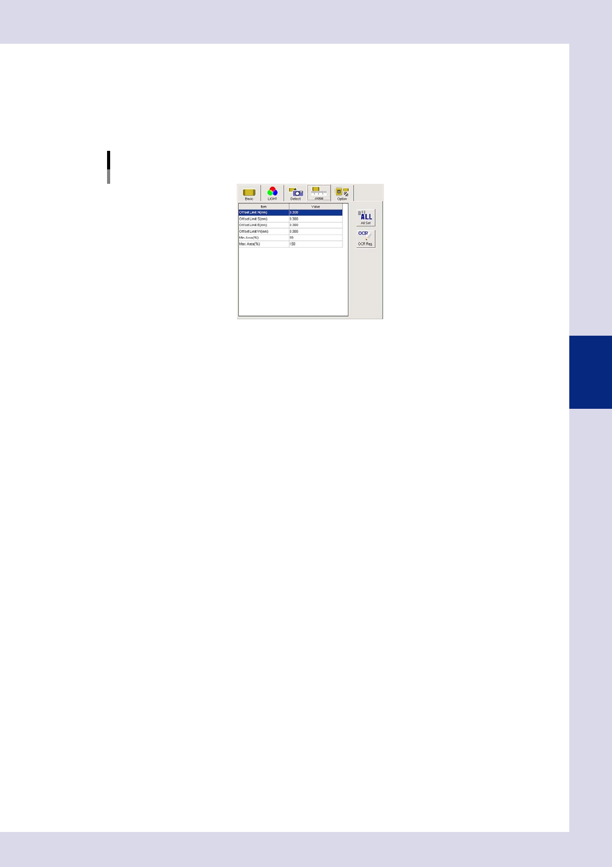
Set the "Judge" parameters.
Open the "Judge" tab and set the following parameters.
"Judge" parameters
Status: Parts Check
24404-P6-00
Offset Limit N - W (mm)
Set the permissible top, bottom, left, right deviation range. An NG result is judged if the detected edge
exceeds the value set here.
Min Area (%)
If the ratio of the detected area to the standard area is smaller than the value set here, then an NG
occurs.
Ref. value 80%
Max Area (%)
An NG result is judged if the ratio relative to the standard area for the detected area exceeds this
value.
Ref. value 120%
Alignment (deg)
An NG result is judged if the detected parts
θ
displacement exceeds this value. By selecting "SKIP", tilt
inspection is not performed.
4
Perform a step test.
1. Press the [Step] button at the "Tuning" tab to perform a test for the created step.
2. When the test result appears, press the [End] button. When doing so, there is no problem if the test
result is "NG".
4-4
4
Inspection status
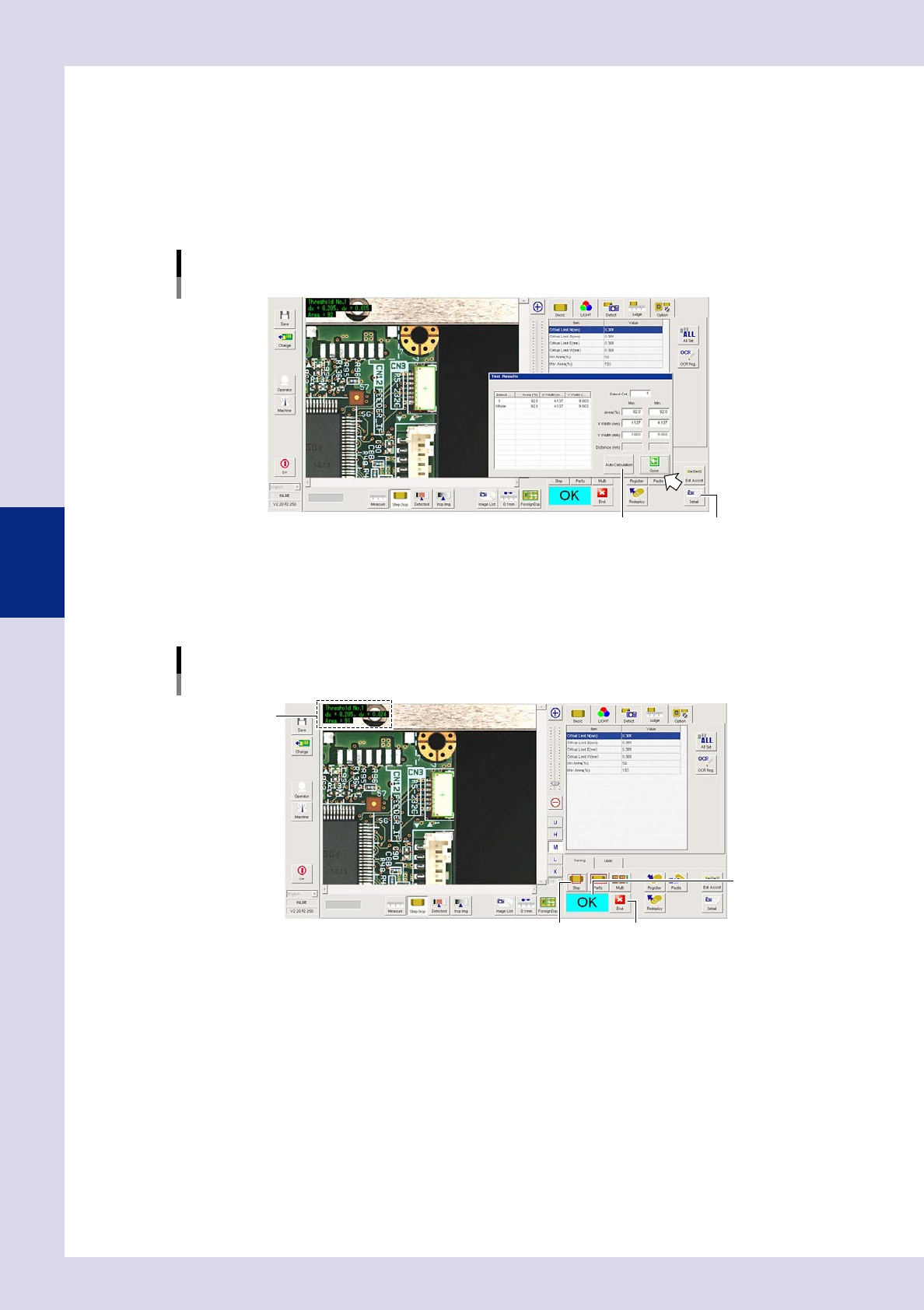
5
Press the [Detail] button.
The "Inspect result" dialog box opens. Press the [Auto Calculation] button. The following items in the
detection conditions parameters are set automatically.
Minimum Detectable Size X
A value 70% of the recognized X width is set.
Minimum Detectable Size Y
A value 70% of the recognized Y width is set.
[Detail] – [Test Results] screen
[Auto Calculation] button [Detail] button
24405-P6-00
6
Perform a step test again.
1. Press the [Step] button at the "Tuning" tab again to perform a step test.
2. Take a note of and check the detection data, and then press the [End] button.
Step test
Inspection data check
Inspection data
[End] button
Test result judgment
[Step] button
24406-P6-00
Detected data
Threshold No. : Threshold No. used for inspection
dx =, dy = : Amount that the step frame center deviates from the detection area center
Area = : Percentage of the detected area relative to the standard area
3. If the test result is not judged correctly, review all parameters while referring to the detection data.
4-5
4
Inspection status
1.2 Electrode Check
Use this inspection mode to measure electrode distances of chip parts, in order to check for missing and
deviated parts or inspect lead fillet.
By setting the "Position-Align-Method" in the basic parameters to "Enable", the step position is aligned from the
electrode check step for this part onward by the amount of parts mounting positional displacement.
1
Make a "step" setting.
1. Create a step frame.
2. Open the "Basic" tab, and set the "Status" in the basic parameters to "Electrode Check".
3. Open the "LIGHT" tab, and set the light sampling type and threshold value in the lighting parameters
that shows the electrodes in red.
Sampling light type reference: Luminance
Status (inspection mode)
Electrode Check
Set to "Electrode Check".
Step frame
24407-P6-00
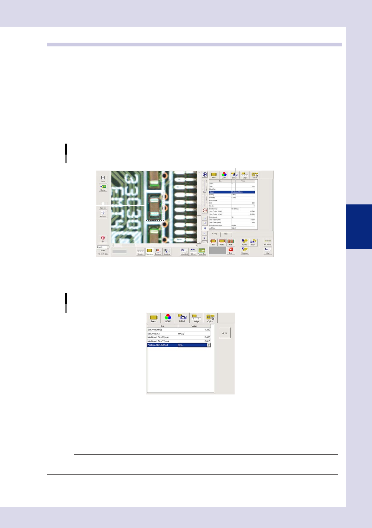
2
Set the "Detect" parameters.
Open the "Detect" tab and set the following items.
"Detect" parameters
Status: Electrode Check
24408-P6-00
Min Area (%)
Select "MAX2" from the drop-down list as the default value.
By setting to "MAX2", the detection area inside the step frame is set to the maximum size and second
size for the object to be inspected (distance measurement), and therefore solder and silk and so on
other than electrodes can be excluded from inspection. (An appropriate value is set at Step 5.)
n
NOTE
Detection areas with ratio relative to the detection area "Std Area (mm
2
)" less than "Min Area (%)" are not subject to
inspection.