YSI_Prog_E - 第167页
4-7 4 Inspection status 4 Perform a step test. 1. Press the [Step] button at the "T uning" tab to per form a test for the created step. 2. When the test result appears, press the [End] button. When doing so, th…
4-6
4
Inspection status
Min Detect Size X, Y (mm)
Sets the minimum detection size for detected electrodes. Enter the default values. (An appropriate
value is set at Step 5.)
•Ifpartsmountedhorizontally
For the X value, enter a width smaller than the Y value minimum width.
Default values: X = 0.04, Y = 0.08
•Ifpartsmountedvertically
For the Y value, enter a width smaller than the X value minimum width.
Default values: X = 0.08, Y = 0.04
Correlation between minimum detection size and measurement direction
If vertical mounting: X value > Y valueIf horizontal mounting: X value < Y value
Horizontal mounting Vertical mounting
23401-P6-00
n
NOTE
By entering the minimum detection size, the direction used to measure distance changes.
3
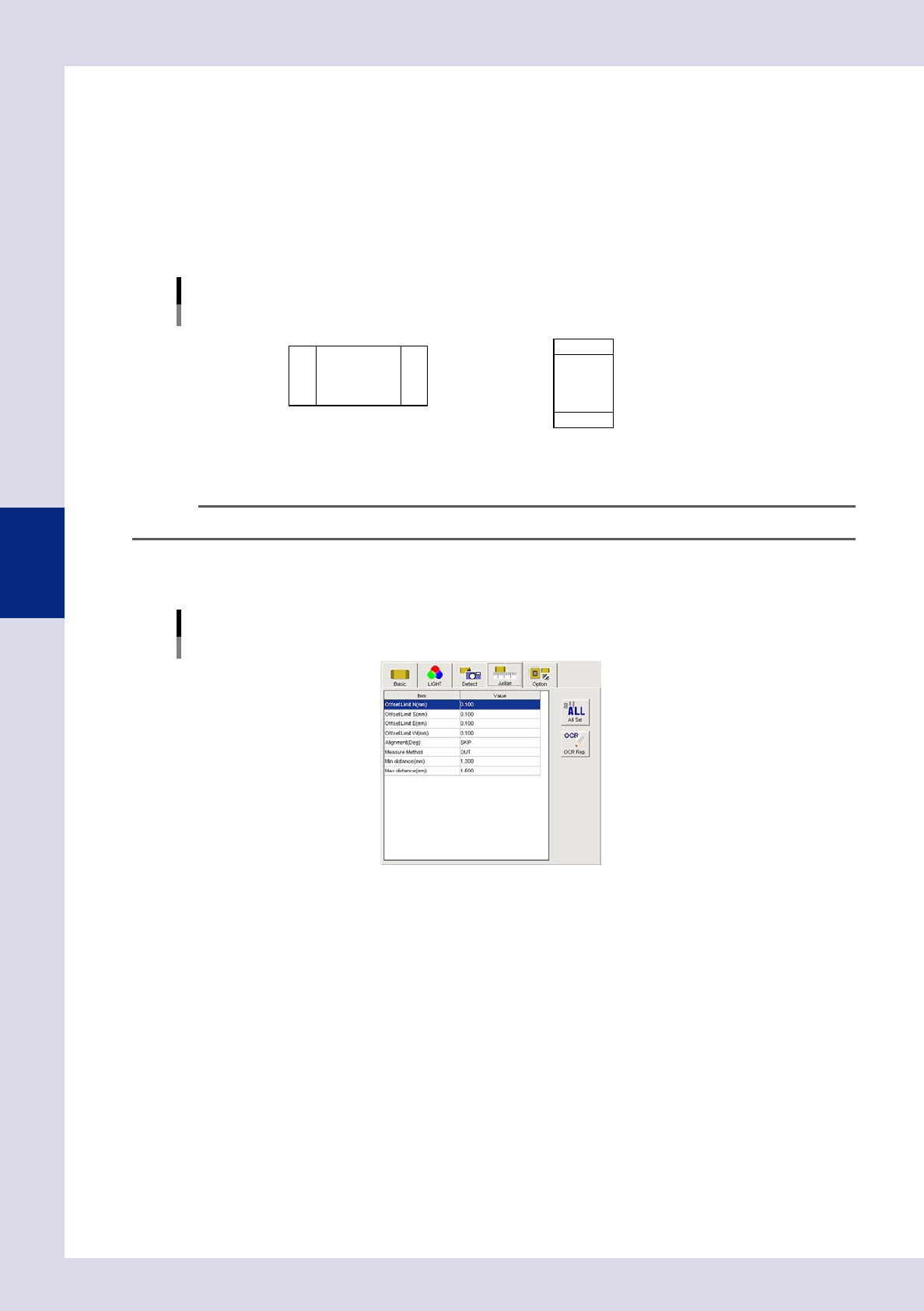
Set the "Judge" parameters.
Open the "Judge" tab and set the following parameters.
"Judge" parameters
Status: Electrode Check
24409-P6-00
Offset Limit N - W (mm)
Sets the allowable positional displacement range in the up, down, left, and right directions. An NG result
is judged if the detected edge exceeds the value set here.
Measure Method
Set the larger difference in distance between when a part does exist and when a part does not exist.
IN : Measures the distance between the inside of electrodes.
OUT : Measures the distance between the outside of electrodes.
Alignment (deg)
An NG result is judged if the detected parts
θ
displacement exceeds this value. By selecting "SKIP", tilt
inspection is not performed.
4-7
4
Inspection status
4
Perform a step test.
1. Press the [Step] button at the "Tuning" tab to perform a test for the created step.
2. When the test result appears, press the [End] button. When doing so, there is no problem if the test
result is "NG".
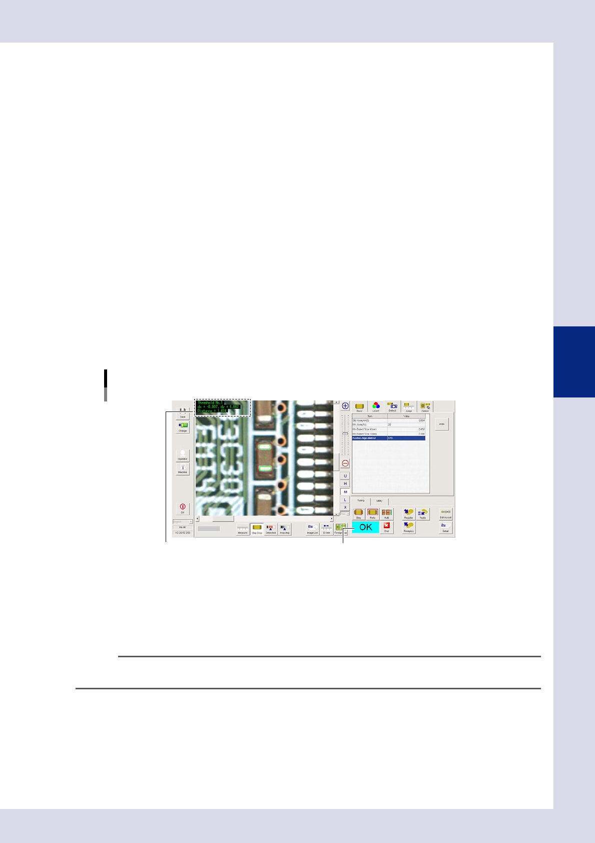
5
Press the [Detail] button.
The "Inspect result" dialog box opens. Press the [Auto Calculation] button. The following detection
conditions parameter and judgment condition parameter items are set automatically.
Detection conditions parameter
Min Area (%)
"20" is set.
Minimum Detectable Size X, Y (mm)
A value 70% of the minimum detection width is set.
Judgment conditions parameters
Min distance (mm)
A value 90% of the recognition distance is set. An NG result is judged if less than the value set here.
Max distance (mm)
A value 110% of the recognition distance is set. An NG result is judged if greater than the value set
here.
6
Perform a step test again.
1. Press the [Step] button at the "Tuning" tab again to perform a step test.
2. Take a note of and check the detection data, and then press the [End] button.
Screen after a step test is finished
Test resultDisplays detected data.
24410-P6-00
Detected data
Threshold No. : Threshold No. used for inspection
dx =, dy = : Amount that the step frame center deviates from the detection area center
Area = : This is the detection object distance. (Unit: mm)
3. If the test result is not judged correctly, review all parameters while referring to the detection data
n
NOTE
Paste a completed step to a missing part position and ensure that an NG result is returned. If judged incorrectly,
review the minimum or maximum distance.
4-8
4
Inspection status
1.3 Polarity Check
This inspection status is used if inspecting the parts mounting angle by recognizing polarity marks on IC partss
and so on.
TIP
• "BrightnessLevel"or"Comparison"inspectionstatusesmaybeappropriateforcertainpolaritymarktypes.
• Byselectingcharacterrecognitionfortheinspectionstatus,selecting"NON"for"AcceptableRotation"inthe
judgment parameters, and then performing an inspection, the parts mounting angle can be inspected.
1
Make a "step" setting.
1. Create a step frame.
When creating a step frame for a circular mark, create a frame which is slightly smaller than the
circumference of the circle.
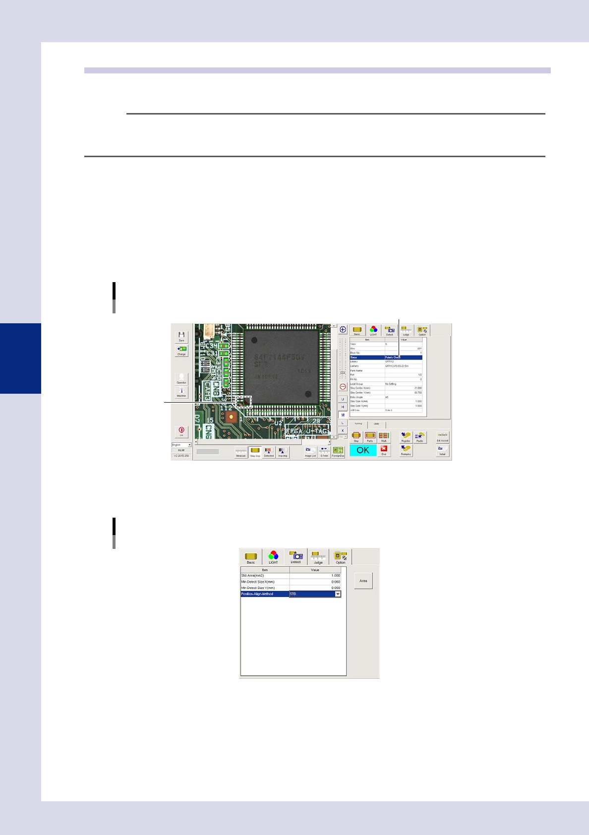
2. Open the "Basic" tab, and set the "Status" in the basic parameters to "Polarity Check".
3. Open the "LIGHT" tab, and set the light sampling type and threshold value in the lighting parameters
so that polarity marks are shown in red.
Sampling light type reference: Color
Status (Inspection mode)
Polarity Check
Set to "Polarity Check".
Step frame
24411-P6-00
2
Set the "Detect" parameters.
Open the "Detect" tab and set the following parameters.
"Detect" parameters
Status: Polarity Check
24412-P6-00
Minimum Detectable Size X, Y (mm)
Sets the minimum size for the object to be inspected. Set default values of X = 0.06, and Y = 0.06. (An
appropriate value is set at Step 5.)