YSI_Prog_E - 第173页
4-13 4 Inspection status 4 Perform a step test. 1. Press the [Step] button at the "T uning" tab to per form a test for the created step. 2. When the test result appears, press the [End] button. When doing so, t…
4-12
4
Inspection status
3
Set the "Judge" parameters.
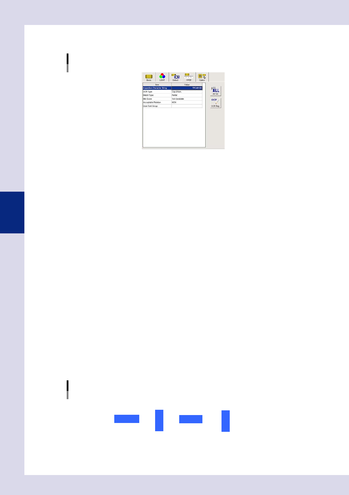
Open the "Judge" tab and set the following parameters.
"Judge" parameters
Status: Character Recognition
24417-P6-00
Inspection Character String
Enter the character string to be inspected. Up to thirteen characters can be entered.
OCR Type
Select the appropriate setting from among "Cap&Num", "Cap", and "Num" (Alphanumeric,
Alphabetic, and Numeric) for the character string to be inspected. In the case of alphabetic
characters, only uppercase letters are recognized.
Match Type
Full : This inspects whether the detected character string completely matches the inspection
character string.
Partial : This inspects whether the detected character string contains the inspection character string.
You can enter a partial character string if you want to inspect only specific characters. If, for example,
only wishing to inspect 7 and 9 from a character string of "3793", enter "79" and set to "Partial". An NG
result is judged if unable to recognize the specified character string.
Min Score
If set to "1st candidate", the object with the highest score among the detection candidate characters
will be inspected. If the character print quality is poor, select small values such as 10 or 20 from the
drop-down list.
Acceptable Rotation
Sets whether to inspect the character angle.
NON : Select this setting when only the specified orientation should be judged to be OK
(normal setting).
Permit 180° : Select this setting for components such as chip resistors where 180° rotation presents
no problem.
Permit All : Select this setting for cases where the specified character presence/absence is the
only criterion and the character string angle is not an issue. However, the inspection
time will take a little longer because the image is rotated during image processing.
Set the character recognition angle in "Entry Angle" in the basic parameters. As shown below, this is the
angle rotated counterclockwise from 0°.
1234
0 degrees
90 degrees 180 degrees 270 degrees
1234
1 2 3 4
1234
Character recognition angles
22402-P6-00
4-13
4
Inspection status
4
Perform a step test.
1. Press the [Step] button at the "Tuning" tab to perform a test for the created step.
2. When the test result appears, press the [End] button. When doing so, there is no problem if the test
result is "NG".
5
Press the [Detail] button.
A "Test Results" screen appears. Take a note of the results and check.
1. The detected character and recognition score (%) are displayed in order of highest degree of
recognition.
2. Review the "Min Score" setting in the judgment conditions parameters based on the recognition
score result.
3. By pressing the [Auto Calculation] button, the following detection conditions parameters are set
automatically.
Character Size X (mm)
The maximum X width in the test results is set.
Character Size Y (mm)
The maximum Y width in the test results is set.
TIP
Depending on the recognition status, there may be times when the "Character Size X, Y (mm)" is best left at "AUTO".
6
Perform a step test again.
1. Press the [Step] button at the "Tuning" tab again to perform a step test.
2. Take a note of and check the detection data, and then press the [End] button.
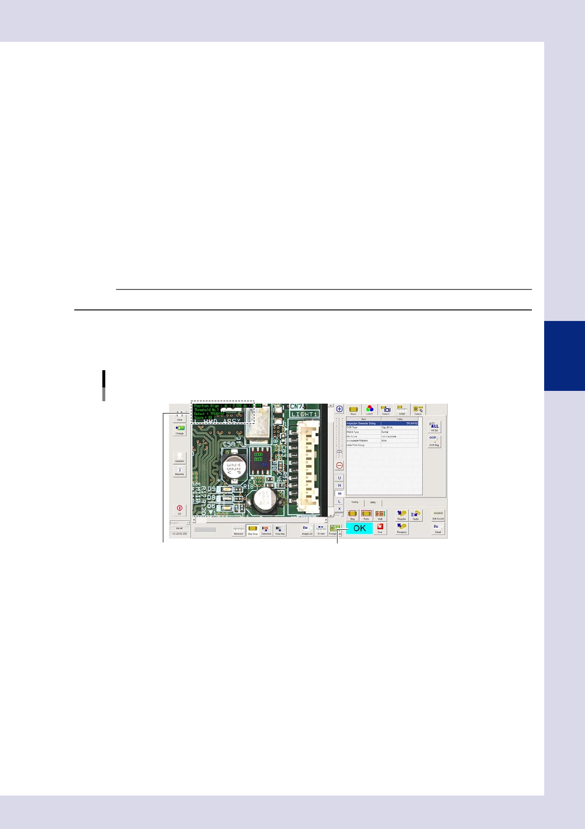
Screen after a step test is finished
Test resultDisplays detected data.
24418-P6-00
Detected data
Threshold No. : Threshold No. used for inspection
Detect : This is the recognized character.
Score : This is the minimum recognition score for recognized characters.
3. If the test result is not judged correctly, review all parameters while referring to the detection data.
4-14
4
Inspection status
1.5 Solder Quantity Check
This inspection status is used to detect solder fillets on chip parts, and to inspect solder quantity.
1
Make a "step" setting.
1. Create a step frame.
2. Open the "Basic" tab, and set the "Status" in the basic parameters to "Solder Quantity Check".
3. Open the "LIGHT" tab, and set the light sampling type and threshold value in the lighting parameters
so that fillets are shown in red.
Sampling light type reference: Shape
Status (inspection mode)
Solder Quantity Check
Set to "Solder Quantity Check".
Step frame
24419-P6-00
2
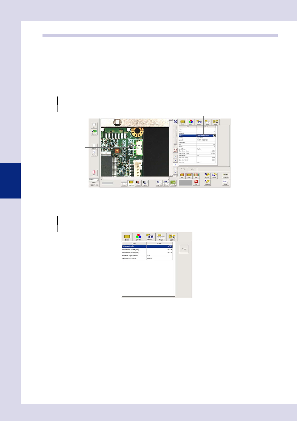
Set the "Detect" parameters.
Open the "Detect" tab and set the following parameters.
"Detect" parameters
Status: Solder Quantity Check
24420-P6-00
Minimum Detectable Size X, Y (mm)
Sets the minimum size for the solder to be inspected. For example, if the step frame is horizontally long,
set X = 0.06 and Y = 0.01, and if the step frame is vertically long, set X = 0.01 and Y = 0.06.